User Manual SICLOCK GPS1000
Order numberr 2XV9450-1AR82-BA
Version 2.0
7
2.
Brief Overview
2.1.
Function
SICLOCK GPS1000 is a modern GPS radio-controlled clock which can be used worldwide for the reception of time
signals from the 24 American GPS satellites. At the output of the GPS1000 antenna head a DCF77 time telegram
with Greenwich Meantime is available.
The advantage of the GPS1000 is that the antenna, GPS receiver and GPS decoder are integrated in the an-
tenna head as one unit and there is therefore no need to lay coaxial cables, nor to separately install the de-
coder together with a power supply.
Both the power supply of the antenna head and also the transmission of the DCF77 time telegram is done via
loop current by means of a shielded twin-core control cable with a maximum length of approx. 1000 meters. The
power supply module GPS1000 PS is at the process end of the control cable. The module feeds the loop current
connection to the antenna head and extracts the DCF77 time telegram. For its own supply it has a long range
power supply of 24 to 230V V/DC or 48-230 V/AC.
SICLOCK GPS1000 does not require parameter settings.
2.2.
Scope of Delivery
•
GPS1000 antenna head E10433-E9910-H100 with integrated electronics and 2,5 m connecting cable
with end splices
•
GPS1000 PS (power supply module) E10433-E0006-H100
(not included in the complete package SICLOCK TC400 with GPS1000, SICLOCK TC100 with GPS1000
and SICLOCK TS with GPS1000)
•
Antenna holding frame for universal mounting, comprising:
antenna stand with base plate and holding arm,
cube with 6 hexagon socket set screws,
sealing cover
•
Allan key for installation
•
Conduit box for connection of control cables
•
Connecting cable to PC COM interface (9-pole SUB D)
•
Operating manual German / English
2.3.
Installation Procedure
1. First find a suitable location for the antenna.
When doing this, please take the following into account:
The antenna head should be able to “see” as much sky as possible and must be installed with the housing
cover upwards, parallel to the sky.
The antenna head should NOT be installed in places where there is lightning hazard! (see chap. 3)
Make sure that there is easy access for servicing! (Electromagnetic interference fields from the plant do not
need to be taken into account as the operating frequency of GPS1000 is above the industrial interference
level.)
2. Mark the drill holes for installing the antenna stand, drill and insert dowels.
3. Make the bore hole for the connecting cable (for wall mounting preferably in the middle underneath the base
plate).
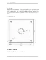
4. Assemble the antenna according to figures 9 and 10 respectively.
5. Thread the cable into the bore hole and screw on the stand. For mounting on flat roofs, use additional IP67-
distribution box and additional control cable to extend if necessary.
6. Inside buildings, install the supplied conduit box near to the cable entry (alternatively, install the lightning
protection module 2XV9450-1AR83 and omit the conduit box).
7. Mount the GPS1000 PS near the system to be synchronized (computer, SICLOCK TM, SPC or similar.) (on DIN
rails, 19 inch frames or in table housing).
8. Control cable provided on site for GPS1000 PS (terminal X2/11,12) for installation of conduit box for the an-
tenna and clamp with antenna connection cable (polarity is not important here).
9. Lay the shield of the control cable on the equipotential busbar in the control cabinet.
10. Set up the power supply connection to GPS1000 PS (terminal X1/13,14,15).
11. Setting up synchronization to the system:
Connection to PC:
via cable supplied for X3 at SICLOCK GPS1000 PS to free COM interface.
(Driver software required: 2XV9450-1AR28).
Connection to SICLOCK TM:
via shielded twin-core control cable from the terminal X2/1,2 at SICLOCK
GPS1000 PS to SICLOCK TM terminal X2/5,6.
Connection to SICLOCK TS:
via shielded twin-core control cable directly from the antenna head (SICLOCK
GPS1000 PS is not necessary) to SICLOCK TS terminal X2/9,10.


