


Siemens Building Technologies
Fire Safety
P/N 315-033290C-7
3
To Install Detector Head:
• Align LED in detector with LED symbol on base and
insert detector into base.
• Rotate detector counterclockwise while gently press-
ing on it until the detector seats fully into base.
• Then rotate the detector clockwise until it stops and
locks in place. Insert optional locking screw (Order
Model LK-11).
To Remove Detector Head:
• Loosen locking screw, if installed. Then rotate the
detector counterclockwise until stop is reached.
• Pull detector out of base.
DETECTOR TESTING
Only qualified service personnel should test. To assure proper
operation of the detector and control panel, both the Sensitivity
and Functional Test should be conducted. The minimum test
schedule may be found in the current edition of NFPA 72 for
installations in the U.S., and CAN/ULC-S537, The Verification of
Fire Alarm Systems, for installations in Canada.
Sensitivity Measurement
The sensitivity of SFPO-11 and SFP-11 detectors can be tested
individually using the SDPU. Refer to the SDPU Manual, P/N
315-033260C.
Functional Test
Perform a functional (Go, No-Go) test by activating the detec-
tor using
Test Gas, P/N 315-282747, following the instruction
on the label. This test is simply used to ensure that smoke
can enter the sensing chamber and alarm the control panel
when the detector reaches the programmed obscuration (con-
centration) level.
The SFPO-11/SFP-11/SFPT-11 detectors can also be tested
individually using the SDPU. Refer to the SDPU Manual, P/N
315-033260C.
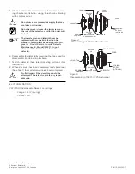
TO INITIATING
CIRCUIT OF
SIEMENS BUILDING
TECHNOLOGIES, INC.
COMPATIBLE
CONTROL UNIT
OPTIONAL
REMOTE
ALARM
INDICATOR
MODELS
RL-HW / RL-HC
TO NEXT BASE
TO NEXT BASE
DO NOT
USE AN
END OF
LINE
DEVICE
DETECTOR BASE
MODEL DB-11
LINE 1**
LINE 2**
5
6
1a
TB1
TB3
TB2
1b
5
6
1a
1b
RELAY*
CONTACTS
3A, 120 VAC
3A, 30 VDC
REMOTE RELAY
BASE MODEL DB-SR
*The relay contacts are shown after System reset, which represents the non-alarm condition.
**SFP-11/SFPT-11/SFPO-11 is a polarity insensitive detector. Line 1 and Line 2 can be either line of the loop.
5+
NO
C
NC
6
–
5+
NO
C
NC
6
–
DO NOT
USE AN
END OF
LINE
DEVICE
Figure 3
Installation and Wiring Diagram
DETECTOR CLEANING AND MAINTENANCE
The control unit automatically indicates the trouble mes-
sage "Maint Alert" for any detector whose smoke chamber
changes to the level where the set sensitivity cannot be
maintained. In such circumstances, the detector may re-
quire cleaning as a result of dust or debris accumulation;
follow the
CLEANING PROCEDURE
steps.
The recommended requirement for detector maintenance
consists of the annual cleaning of dust and debris from the
detector head. Cleaning program intervals should be geared
to the individual detector environment.
If the fire alarm control panel is connected to a
Fire Department, etc., or activates an external
system (fire extinguishing, etc.), disarm the
appropriate outputs before servicing to
prevent activation. Be sure to reset and
rearm the system at completion of servicing.
Notify facility personnel that the system is
being serviced so that any alarm soundings
can be ignored during the period of service.
CLEANING PROCEDURE*
(See Figures 4 and 5)
1. Notify the proper personnel that the fire alarm system
is being serviced.
2. Remove the detector to be cleaned from its base. (See
To Remove Detector Head
on page 3.)
3. Using a small blade screwdriver, remove the cover from
the rest of the detector by releasing the 2 cover tabs
located on the outside of the cover. Separate the foam
screen from the cover.
4. Remove the labyrinth from the sensing chamber by
squeezing the labyrinth sides along the release axis and
pulling out. Carefully remove the labyrinth/thermal holder
assembly being sure not to damage or disconnect the
thermal wires.
* Model SFPT-11 is not field cleanable.