s
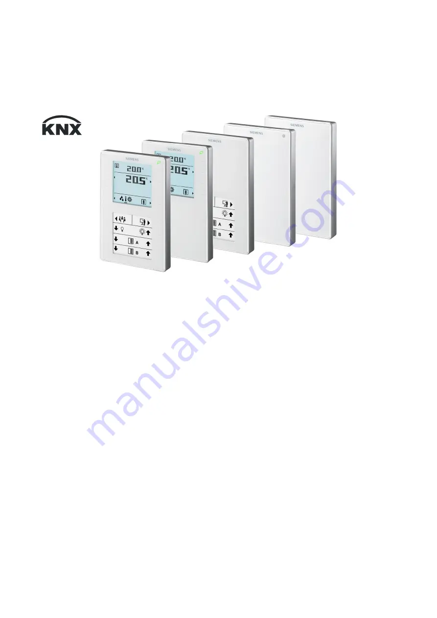
QMX3.P37 QMX3.P34/P74 QMX3.P02 QMX3.P70 QMX3.P30/P40
Wall-mounted sensors and room operator units for
KNX/ETS and KNX/ACS
Technical principles
CM2N1602en_05 2018-09-14
Building Technologies
Page 1: ...s QMX3 P37 QMX3 P34 P74 QMX3 P02 QMX3 P70 QMX3 P30 P40 Wall mounted sensors and room operator units for KNX ETS and KNX ACS Technical principles CM2N1602en_05 2018 09 14 Building Technologies ...
Page 2: ...ecific regulations 11 2 3 Notes on EMC optimization 11 3 Mounting and electrical installation 12 4 Functionality Use 16 4 1 Overview 16 4 2 Use 17 4 3 Display elements and buttons 18 4 4 Functions 19 4 4 1 Measuring 19 4 4 2 Control and operation 20 4 5 Application examples 22 4 5 1 Room temperature control and operation via QMX3 22 4 5 2 Presence dependent room climate control with operation of a...
Page 3: ... Relative humidity visualization 39 5 5 10 Display on QMX3 P70 Air quality indication LED 39 5 5 11 Operation and display air quality 40 5 5 12 Operation of light shading and scenes 40 5 6 Examples for the operation of touch keys and display elements 42 6 ACS engineering 44 6 1 Engineering 44 6 2 Commissioning 44 6 3 ACS Parameter description 46 6 3 1 Communication 46 6 3 2 Universal temperature s...
Page 4: ...ed or not registered trademarks of the owner listed in the table These trademarks will not be indicated elsewhere in the text e g by use of symbols such as and due to the reference in this Section and to facilitate the reading of the text This document may be duplicated and distributed only with the express permission of Siemens and may be passed only to authorized persons or companies with the re...
Page 5: ...eam in the headquarters fieldsupport zug ch sbt siemens com if no local POC is available Siemens assumes no liability to the extent allowed under the law for any losses resulting from a failure to comply with the aforementioned points or for the improper compliance of the same 0 3 Abbreviations and naming conventions Abbr Description ACS790 Engineering Tool for Synco devices ETS Engineering Tool S...
Page 6: ...107 X X X QMX3 P34 S55624 H105 X X X QMX3 P74 S55624 H106 X X X X X X QMX3 P37 S55624 H108 X X X X X Accessories QMX3 MP1 S55624 H110 Base plate for conduit box cavity wall box for 68 mm diameter hole 20 pcs per package 1 2 Equipment combinations The room operator units are KNX certified and can be connected to all suitable KNX devices if the appropriate communication objects are available in the ...
Page 7: ...xes The screw head height must not exceed 3 mm The device C incorporates a KNX PL Link plug a tool plug and depending on the type sensor element keys LCD panel window for the label The cable can be pushed into channels on the rear A KNX plug is enclosed with the devices The optional metal reinforced base plate QMX3 MP1 B1 serves for two purposes It is more rigid so that it does not bend when fixed...
Page 8: ...ontaining the unique KNX ID as alphanumeric and barcode display The address label can peeled off the device during mounting and stuck to a floor plan or similar The floor plan thus contains the assignment of KNX IDs and physical installation location This greatly simplifies the following steps In addition the procedure serves as the basis for the recommended engineering and commissioning process I...
Page 9: ...ounted sensors and room operator units for KNX ETS and KNX ACS CM2N1602en_05 Building Technologies Devices 2018 09 14 1 5 Dimensions 133 4 115 88 4 18 1602M01_01 80 5 7 8 5 60 28 2 26 5 26 13 1 56 5 17 5 28 2 3 5 1602M02 ...
Page 10: ...spose of the components compatible with current environmental recycling and disposal technologies Observe all local applicable laws The aim is to reuse as much of the basic materials as possible at the lowest possible environmental impact To this end note any material and disposal notes in individual components 1 6 2 Environmental declaration The product environmental declaration CM2E1602 contains...
Page 11: ...dard Do not open the device The device is maintenance free Only the manufacturer can repair the device 2 3 Notes on EMC optimization When setting up cable ducts separate strongly interfering cables from susceptible entities Interfering cables Motor cables especially from motors supplied by inverters energy supplying cables Susceptible entities Control cables low voltage cables interface cables LAN...
Page 12: ...ded height 1 50 m above floor Do not mount the devices in recesses shelves behind curtains or doors or above or near heat sources Avoid direct solar radiation and drafts Seal the conduit box or the installation tube as air currents can affect sensor readings Adhere to allowed ambient conditions Mounting instructions M1602 are enclosed with the devices Service LED red Tool plug Programming pin The ...
Page 13: ...r may enter the device and cause faulty temperature readings by the internal sensor 1 Fixing the box on the cavity wall 2 Fixing the QMX3 MP1 base plate on the box using 2 screws 3 The gray foam plate removable compensates for the jutting edge of the box so that the plate is aligned with the wall Wall mounting Remove the breakout on the housing before putting the cable into the gaining channel 4 w...
Page 14: ... a distance of 30 mm from above 20 mm from below to the base plate so that the device can be snapped onto the base plate Sample icons are available in the label template M1602 1 Download from www siemens com gamma td Information e g on room operator unit location or on room type free text Max 6 59 2 0 15 1602z110 54 0 15 Dismounting service Labels for QMX3 P02 QMX3 P37 Insert label 1602Z106 1602J1...
Page 15: ...orrect cables for the KNX bus Do not interchange the wires of the KNX cable The red terminal is for KNX The gray terminal is for KNX Observe all local installation regulations The devices are not protected against accidental connection to AC 230 V Information in topology and addressing in KNX networks is available in document KNX bus 4 The following information requires electrical installation as ...
Page 16: ... 2018 09 14 4 Functionality Use 4 1 Overview Typ Funktion Temperature sensor Humidity sensor CO 2 sensor Air quality indicator with LED Display and operation with touchkeys Operation of light shading and scenes Sensors QMX3 P30 X QMX3 P40 X X QMX3 P70 X X X X Room operator units QMX3 P02 X X QMX3 P34 X X QMX3 P74 X X X X QMX3 P37 X X X ...
Page 17: ...th varying occupancy due to time or number of people such as in museums movie theaters offices meeting rooms class rooms auditoriums hospitals living spaces The room operator units control and operate Room temperature via PID controller Humidity via threshold value Air quality via threshold value Fan stages independent of temperature air quality and humidity control functions Room operating modes ...
Page 18: ...lay of the present fan speed when automatic Adjusting the fan speed using key 3 or keys 3 and 7 if operation of room operating mode is disabled Display of the room operating mode when automatic Adjusting the room operating mode using key 7 Navigation toggle the display setpoint setting between temperature humidity CO2 using key 4 The black bar points to the displayed information Operation of the o...
Page 19: ... control The room operator units acquire the relative humidity in the room with the aid of a humidity sensing element integrated in the front module The relative room humidity can be transmitted to other bus members and serves in KNX as control variable of the integrated ventilation controller The room operator units determine the CO2 concentration via infrared absorption measurement NDIR The sens...
Page 20: ...vided to control the room temperature The controller supplies a continuous or a pulse width modulated PID signal for one heating and one cooling actuator The room temperature setpoints for the two operating modes heating and cooling as well as a blocking object can be set using the touchkeys and the display or received from the bus Changeover to the operating mode Heating Cooling is automatic Pres...
Page 21: ...t can be extended Extensions are set between 5 and 120 minutes in ETS This function can be activated or deactivated key 8 see section 4 3 The following table provides information on assessing room air quality based on the determined CO2 concentration ppm Typical CO2 concentration 400 Outside air 700 City air 1000 Comfort limit 1500 Ventilation strongly recommended 2000 Inacceptable indoor air qual...
Page 22: ...dividual or button pairs and related LEDs can be parameterized individually See Section 3 for button labels Common functions such as switching On Off toggle or sending of values percentage dimming or blinds control 8 bit scene control with without memorize are supported 4 5 Application examples Below are a few typical application examples for the QMX3 P30 P34 P70 and P74 room operator units 4 5 1 ...
Page 23: ...23 04 7 Universal dimmer N 528 31 with sub module N 528 41 8 Thermal drive actuator N 605 for up to 6 rooms 9 Thermal valve actuator STA23 up to 4 per room This application is especially suitable for rooms with several heaters e g in offices lecture halls or conference rooms The room operator unit 1 measures and controls the room temperature and sends the control signal to the thermal actuator 8 v...
Page 24: ... combination of components 1 Room sensor QMX3 P70 including Temperature sensor Humidity sensor CO2 sensor 2 Air handling controller RMU7x0B The room operator unit 1 measures the room temperature the room humidity and the CO2 concentration and passes these values on to the controller 2 via the KNX bus The controller controls temperature humidity and air quality of the corresponding room based on th...
Page 25: ...If the service LED lights up the polarity of the wires is correct Pushbutton actuation Meaning Short 2 s Switch over to programming mode or acknowledge display of a connection test No functions are executed when the programming button is pressed longer 2 s to 5 s Long 20 s Note Reset to factory settings This operation resets all user preference data and parameter settings to factory default This o...
Page 26: ...m temperature value from the integrated sensor Value of the outside temperature sensor See object 53 Must be placed in a group address to display the value on the display In the operating mode Auto the controller independently changes over between heating and cooling mode But only either the cooling or heating mode is always active If the object room temperature controller is enabled the operating...
Page 27: ...red Units with display Must be placed in a group address to display operation symbol on the display These objects available only when PID control is enabled Units with display Objects must be placed in a group address to display open window symbol on the display corresponds to object 55 for units with display corresponds to object 56 for units with display This is a setpoint set It can be used to ...
Page 28: ...tching points apply as long as no value is received from the bus In manual mode obj 30 1 Manual a setpoint is received via this object and outputted directly as modulating positioning signal object 36 Changing over to the manual mode permits receipt of a manual setpoint Obj 29 for the modulating positioning signal Obj 36 Otherwise the configured positioning signals for the applicable stage are out...
Page 29: ...on exceeds the switching point CO2 The positioning signal CO2 is switched off again for CO2 concentration switching point CO2 hysteresis The positioning signal configured to the state is outputted if CO2 concentration exceeds a switching point CO2 The positioning signal once again outputs the value of the next smaller stage CO2 concentration switching point CO2 hysteresis Provides the CO2 value fr...
Page 30: ...tuator controller Units with display Objects must be placed in a group address to display symbols Displays present controller state heating or cooling with symbols No symbol is displayed in the off state Units with display Must be placed in a group address to display symbols External outside temperature sensor value Units with display Must be placed in a group address to display the value Comfort ...
Page 31: ...g on off 1 001 1 bit CWT X X 91 Button A2 send value 5 001 1 byte CT X X 92 Button A2 2nd obj switching on off 1 001 1 bit CWT X X 93 Button A2 send value 2 5 001 1 byte CT X X 94 Button A2 switching on off 1 001 1 bit CWT X X 95 Button A2 dimming brighter darker 3 007 4 bit CT X X 96 Button A2 blind up down 1 008 1 bit CT X X 97 Button A2 slats stop open close 1 007 1 bit CT X X 98 Button A2 8 bi...
Page 32: ...hing on off 1 001 1 bit CWT X X 121 Button C1 send value 5 001 1 byte CT X X 122 Button C1 2nd obj switching on off 1 001 1 bit CWT X X 123 Button C1 send value 2 5 001 1 byte CT X X 124 Button C1 switching on off 1 001 1 bit CWT X X 125 Button C1 dimming brighter darker 3 007 4 bit CT X X 126 Button C1 blind up down 1 008 1 bit CT X X 127 Button C1 slats stop open close 1 007 1 bit CT X X 128 But...
Page 33: ...145 Button D1 dimming brighter darker 3 007 4 bit CT X X 146 Button D1 blind up down 1 008 1 bit CT X X 147 Button D1 slats stop open close 1 007 1 bit CT X X 148 Button D1 8 bit scene recall save 18 001 1 byte CT X X 149 Status LED D1 on off 1 001 1 bit CRWU X X Function button pair 4 button 2 150 Button D2 switching on off 1 001 1 bit CWT X X 151 Button D2 send value 5 001 1 byte CT X X 152 Butt...
Page 34: ... X X X 18 21 Window state Displays the symbol Open window only during active PID control X X X 65 Fan default value Displays the fan speed that can be changed on the display The value can also be received via bus when adjusted on another device X X X 66 Fan mode Auto Manual Displays the fan operating mode that can be changed on the display The value can also be received via bus when adjusted on an...
Page 35: ...es two control algorithms one for continuous mode 0 100 and one for PWM mode On Off The mode is selected via parameter Control value type The control value type is identical for all operating modes In continuous mode the associated PWM output is On at continuous control value 0 In PWM mode cycle time and pulse width are adapted to the type of heating cooling the setpoint and the measured room temp...
Page 36: ...0 8K Radiator heating fast 2 K 3600s 540s 0 1K 0 8K Floor heating slow 2 K 7200s 540s 0 1K 0 8K Floor heating fast 2 K 5400s 540s 0 1K 0 8K PID parameter set for the cooling sequence Cooling type Xp TiN TiV Nz SD Chilled ceiling 2 K 5400s 450s 0 1K 0 8K Floor cooling 2 K 5400s 540s 0 1K 0 8K Regardless of the setting of the control signal type PWM or continuous all 4 objects are switched on The op...
Page 37: ...h X X X X X X X Default switching point stage 3 r h 0 100 90 r h X X X X X X X Hysteresis 2 3 4 5 7 10 5 r h X X X X X X X If room humidity exceeds a switching point r h the control value r h for the respective stage is switched on Control value r h is switched off again when room humidity switching point r h hysteresis Control value stage 0 0 100 0 X X X X X X X Control value stage 1 stage 0 0 10...
Page 38: ...CO2 concentration exceeds a switching point CO2 the control value CO2 for the related stage is switched on The control value CO2 is again switched off if the CO2 concentration returns to switching point CO2 hysteresis Control value stage 0 0 100 0 X X X X X X X Control value stage 1 stage 0 0 100 35 X X X X X X X Control value stage 2 stage 1 0 100 70 X X X X X X X Control value stage 3 stage 2 0 ...
Page 39: ...eration Room Operating Mode yes no X X X Operation Room Occupancy Mode yes no X X X Display Window state visualization yes no X X X Display Heating Cooling indication yes no X X X Operation fan Speed yes no X X X Fan type 1 speed 3 speed Variable speed X X X Minimum fan speed variable speed 0 100 0 X X X Maximum fan speed variable speed 100 0 100 X X X Regardless of whether the Display Window stat...
Page 40: ...it value LED display object independent status object Action falling edge Off On At Send percentage value Send 8 Bit value Object independent LED constant value off on orientation light Short button pressure Action short button pressure Off On At Send percentage value Send 8 Bit value Status object LED activation Off On On Off Long button pressure Long button pressure via send 2nd object No Yes Ac...
Page 41: ...Off On On Off 2 button solar protection blinds control No LED display Action button pair left step up drive up right close down Long button pressure 0 5 6 0s move to end positions Solar protection blinds control can be individually modified for operation The factory setting is 2 buttons next to one another e g 9 Stop step up move up and 13 Stop step down move down If desired this assignment can be...
Page 42: ...gle the display between outdoor and indoor temperature Keys 2 and 6 Room temperature setpoint adjustment absolute Keys 3 4 and 5 No function no arrow symbols are displayed Key 7 Toggle the room operating mode in Auto mode the present operating mode is displayed Key 8 Presence key or Comfort extension Key 1 No function as only room temperature is displayed Keys 2 and 6 Room temperature setpoint adj...
Page 43: ... GOOD OKAY or POOR Keys 2 3 5 6 7 and 8 No function Key 4 Toggle the display pages between temperature humidity and CO2 Key 1 Toggle the display between outdoor and indoor humidity Keys 2 and 6 Room humidity setpoint adjustment absolute Keys 3 5 and 7 No function Key 4 Toggle the display pages between temperature and humidity Key 8 Presence key or Comfort extension Air quality CO2 Humidity and pre...
Page 44: ...able parameters will vary Prior to commissioning all devices must be mounted as per the mounting instructions 2 and connected to bus cabling If available pushbuttons and external temperature sensors must also be connected to the device Bus cabling must be tested Pushbutton actuation Meaning Short 0 5 s Switch over to programming mode or acknowledge display of a connection test No functions are exe...
Page 45: ...Write Enter a physical address and short description for the selected room operator unit Close the Address assignment dialog by clicking Write Repeat these steps for all room operator units to be commissioned Then Continue parameterization in ACS790 The sensor can be operated in both communication modes at the same time To do this commissioning with both ACS and ETS is required Only the sensor val...
Page 46: ...nding zone for KNX ACS Sensor correction 5 5K in 0 1K steps 0K Correction of universal temperature sensor value 6 3 3 Room humidity sensor Designation Values Description LTE transmission zone 1 4095 Sending zone for KNX ACS 6 3 4 Room air quality sensor Designation Values Description LTE transmission zone 1 4095 Sending zone for KNX ACS Altitude above sea level m 0 3000 m 0 m Entry of altitude abo...