QFA1000, QFA1001 Room Hygrostats
Technical Instructions
Document Number 155-708
July 19, 2010
Siemens Industry, Inc.
Page 3
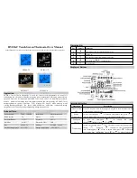
Operating Elements
1
Setpoint knob with scale – only with QFA1001
2
Setpoint setting spindle
3
Scale for setpoint adjustment with QFA1000
Figure 2. Operating Elements.
Mounting Notes
Mounting Choices
The base has cable entries at the rear for mounting the room hygrostat on recessed
conduit boxes. For wall mounting, appropriate holes at the top or bottom can be
knocked out.
Mounting Location
The hygrostat should be mounted on an inner wall approximately 4.9 feet (1.5 m) above
the floor and at least 1.6 feet (0.5 m) from the closest wall.
Mount the unit where there is a natural circulation of room air (do not mount near drafts,
in corners, behind curtains, too close to doors and windows, or on an outer wall).
Sources of heat and refrigeration (radiators, computers, televisions, concealed heating
pipes, hot or cold water pipes) must be at an adequate distance.
The hygrostat should not be exposed to direct sunlight.
Mounting Instructions
Installation Instructions for the room hygrostat are available online.
Specifications
Functional data
Setpoint range
30 to 90% rh
Temperature operating range
32°F to 122°F (0°C to 50°C)
Humidity measuring element
Stabilized plastic band
Control mode
Two-position
Time constant (v = 0.2 m/s)
Approximately 5 minutes
Switching differential
See
Product Numbers
Setting accuracy
+ 5% rh (can be improved by
calibrating
on
site)
Temperature influence
+ 0.5% rh/K
Humidity calibration at
55% rh, 73°F (23°C)
Long-term stability
Approximately
−
1.5% rh/a
Type of switch
Potential-free microswitch (SPDT)
Contact rating
Maximum
5 (3) A, 24 Vac/Vdc
Minimum
100 mA, 24 Vac/Vdc
Protective data
Degree of housing protection
P 20 to EN 60 529
Safety class
II to EN 60 730
Electrical connection
Screw terminals for
Maximum 2 × 16 AWG


