Siemens Powers SW 141 Series Technical Instructions Download Page 5

SW 141 Differential Static Airflow Switches 

Technical Instructions  


Document Number 155-052P25 


June 17, 2010 

Information in this publication is based on current specifications. The company reserves the right to make changes in specifications and models as 
design improvements are introduced. Powers is a registered trademark of Siemens Industry, Inc. Other product or company names mentioned 
herein may be the trademarks of their respective owners. © 2010 Siemens Industry, Inc. 


Siemens Industry, Inc.  

Building Technologies Division 
1000 Deerfield Parkway 
Buffalo Grove, IL  60089-4513 
U.S.A. 

Your feedback is important to us. If you have 
comments about this document, please send them 
to 

SBT_technical.editor.us.sbt@siemens.com


Wiring Diagrams, 
Continued 


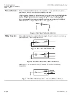
Figure 8.  Auto Reset Switches to Prove Insufficient Airflow or Pressure. 
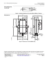
Dimensions 

SW000098R1

Low

Pressure

Inlet

3.88
(98)

0.71

(18)

0.78

(20)

High

Pressure

Inlet

6.13

(156)

2.81

(71)

3.25

(82)

3.25

(82)

1.38

(35)

0.44

(11)

0.19

(5)

dia

hole

1.63

(41)

1.94 (49)


Figure 9.  Dimensions in Inches (Millimeters). 


Document No. 155-052P25 

Printed in the U.S.A. 

Page 5 


Summary of Contents for Powers SW 141 Series

Page 1: ... used for applications requiring safety lock out shut down of the fan The switch can be used on the fan discharge positive pressure fan inlet negative pressure or across the fan differential pressure to detect excessively high positive pressures or low negative pressures and turn off the fan before damage occurs to ducts or dampers Product Numbers Table 1 Product Number Setpoint Range Field Adjust...

Page 2: ...One conduit size 1 2 inch Sample line connectors Two connectors complete with nuts and ferrules which accept 1 4 inch OD 6 4 mm copper or poly tubing Material Aluminized steel Agency certification U L MFHX File MH9888 CSA 1811M25 Weight 1 lb 0 45 kg Dimensions See Figure 9 Accessories High accuracy static pressure sensor 269 062 Static pressure sensing kit 189 142 Operation The diaphragm operates ...

Page 3: ...ure switch Connect the highest static pressure line to the high inlet and the lowest static pressure line to the low inlet marked on the case and Figure 2 141 0518 141 0574 141 0575 Figure 2 Switches with Covers Removed Setpoint Adjustment Each switch is factory set at the minimum setpoint See Table 1 1 To increase the setpoint turn the adjustment screw clockwise as shown in Figure 2 and Figure 3 ...

Page 4: ...he pressure inside a pipe or duct and comparing it to the air outside ambient the pipe or duct is an example of static pressure measurement A sensor measuring the pressure differential across a pump or chiller measures velocity pressure Figure 4 Pitot Tube Part Number 269 062 Wiring Diagrams Before setpoint pressure is applied to the diaphragm the switch contact is in a normally closed position as...

Page 5: ...ve owners 2010 Siemens Industry Inc Siemens Industry Inc Building Technologies Division 1000 Deerfield Parkway Buffalo Grove IL 60089 4513 U S A Your feedback is important to us If you have comments about this document please send them to SBT_technical editor us sbt siemens com Wiring Diagrams Continued Figure 8 Auto Reset Switches to Prove Insufficient Airflow or Pressure Dimensions SW000098R1 Lo...

Reviews: