SW 141 Differential Static Airflow Switches
Technical Instructions
Document Number 155-052P25
June 17, 2010
Siemens Industry, Inc.
Page 3
Installation,
Continued
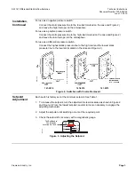
For use as a negative pressure switch:
Connect the static pressure line to the low inlet (marked on the case and Figure 2)
and leave the high inlet open to the atmosphere.
For use as a positive pressure switch:
Connect the static pressure line to the high inlet (marked on the case and Figure 2)
and leave the low inlet open to the atmosphere.
For use as a differential pressure switch:
Connect the highest static pressure line to the high inlet and the lowest static
pressure line to the low inlet (marked on the case and Figure 2.)
141-0518 141-0574
141-0575
Figure 2. Switches with Covers Removed.
Setpoint
Adjustment
Each switch is factory set at the minimum setpoint. See Table 1.
1. To increase the setpoint, turn the adjustment screw clockwise as shown in Figure 2
and Figure 3. From the lowest setpoint, several turns are necessary to engage the
adjusting mechanism.
2. Adjust the setpoint until switching occurs at the required point.
3. Check the setpoint for accuracy with a magnahelic gauge.
SW0096R1
3.0
.05
6.0
12.0
9.0
WC
"
The Red Band Is
The Setpoint
Location On The Scale
Figure 3. Adjusting the Setpoint.


