background image

5 / 9 

Siemens 

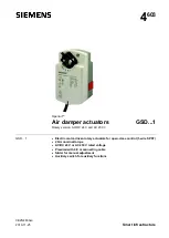
Air damper actuators GSD...1 

CE2N4603en 

Smart Infrastructure 


2019-11-25 

Mechanical design 

 
Fiberglass-reinforced plastic  
Maintenance-free, noise-free 

Engineering notes 

This section explains general and system-specific regulations for mains and 
operating voltages. It also contains important information on your own safety and 
that of your plant. 

Use these actuators as described in the basic system documentation for the 
applied control systems. In addition, take account of all actuator-specific features 
and conditions as described in the brief description on the front page of this data 
sheet (bold print) as well as the sections "Use", "Engineering notes", and 
"Technical data". 

Sections flagged with the warning symbol to the left contain safety-related 
requirements and restrictions that must be adhered to at all times to prevent 
physical injury and equipment damage. 

Operate the actuators only on safety extra-low voltage (SELV) or protective extra-
low voltage (PELV) as per HD 384. 

The actuators are double-insulated and there is no connection for the protective 
ground. 

Apply only mains voltage or protective extra-low voltage to the switching outputs of 
the auxiliary switch. Mixed operation is not allowed. Operation at various phases is 
not allowed. 

Do not open the actuators! 

  The actuators are maintenance-free. 

  Only the manufacturer may carry out repair work. 

  Opening the actuator will void the warranty. 

Up to 10 actuators of the same type can be electrically wired in parallel; cable 
length and cable cross-sections must be observed. 

Selection of the actuator depends on several torque factors. After obtaining the 
damper torque rating (Nm/m²) from the manufacturer and determining the damper 
area, calculate the total torque required to move the damper as follows: 

Non-spring return damper actuators: 
 

IF total torque (SF¹):


Use type:


2 Nm 

GSD…1.1A / GSD…6.1A (2 Nm) 
GXD…1 (1,5 Nm) 


5 Nm 

GDB…1 (5 Nm) 


10 Nm 

GLB…1 (10 Nm) 


15 Nm 

GEB…1 (15 Nm) 


25 Nm 

GBB…1 (25 Nm) 


35 Nm 

GIB… 1 (35 Nm) 

 
¹ Safety factor SF: When calculating the required torque, non-definable variables 
such as slight misalignment, damper age, etc. must be included as a safety factor. 
We recommend a safety factor of 0.8 (or 80 % of the torque characteristic). 

Basic components 

Housing 
Gear train 

STOP 

Intended use 


 AC/DC 24 V supply 

 AC 230 V supply 

 Auxiliary switch 

CAUTION 

Electric, parallel 
connection of actuators 

Required actuator type 

Summary of Contents for OpenAir GSD 1 Series

Page 1: ... Rotary version AC DC 24 V and AC 230 V Electric motor driven rotary actuators for open close control 1 wire SPST 2 Nm nominal torque AC DC 24 V or AC 230 V rated voltage Prewired with 0 9 m connecting cable Slider for manual adjustment Auxiliary switch for auxiliary functions GSD 1 ...

Page 2: ...ends on the actuator s mounting position on the damper shaft Slider Pressing the slider allows for manual actuator adjustment Auxiliary switch GSD 6 1A Set switching points at 5 or 85 1 wire SPST Single pole single throw Technical data Operating voltage AC frequency Operating voltage DC AC 24 V 20 50 60 Hz DC 24 V 15 Power consumption GSD121 1A GSD126 1A running holding 2 VA 1 5 W 1 VA 0 5 W Safet...

Page 3: ...3 9 Siemens Air damper actuators GSD 1 CE2N4603en Smart Infrastructure 2019 11 25 Mechanical life 25 000 cycles ...

Page 4: ...ondensing IEC 721 3 1 Class 1K3 32 50 C 95 r h Mechanical conditions Class 2M2 Product safety Automatic electrical controls for household and similar use IEC EN 60 730 2 14 Type 1 Electromagnetic compatibility Application For residential commercial and industrial environments EU Conformity CE A5W00004362 1 RCM Conformity A5W00004363 1 Product environmental declaration 2 CM2E4604E 1 Actuator W H D ...

Page 5: ...y mains voltage or protective extra low voltage to the switching outputs of the auxiliary switch Mixed operation is not allowed Operation at various phases is not allowed Do not open the actuators The actuators are maintenance free Only the manufacturer may carry out repair work Opening the actuator will void the warranty Up to 10 actuators of the same type can be electrically wired in parallel ca...

Page 6: ...e and mount the actuator are listed in the mounting instructions supplied with the actuator Mount the actuator in a position which ensures easy access to the cables and to the shaft adapter See Dimensions Information on minimum length and diameter for the damper shaft is available in the Technical data section Pressing the eject button allows you to manually adjust the actuator Disposal The device...

Page 7: ...r securely to avoid twisting and blocking of the actuator Check to ensure that the cables are connected in accordance with the plant wiring diagram see Wiring diagrams The operating voltage AC DC 24 V SELV PELV or AC 230 V must be within the tolerance values Power supply AC DC 24 V wires red 1 black 2 Positioning signal AC DC 0 V Wire orange 7 ON Wire orange 7 OFF Actuator turns counter clockwise ...

Page 8: ...em potential AC DC 24 V G0 2 black BK System neutral Y 7 orange OG Positioning signal counter clockwise AC DC 0 V GSD321 1A GSD326 1A AC 230 V L 3 brown BN Phase AC 230 V N 4 blue BU Neutral conductor Y 7 white WH Positioning signal counter clockwise AC 230 V Auxiliary switch Q11 S1 gray red GYRD Switch A input Q12 S2 gray blue GYBU Switch A NC contact Q14 S3 gray pink GYPK Switch A NO contact Q21...

Page 9: ... 11 25 Dimensions Issued by Siemens Switzerland Ltd Smart Infrastructure Global Headquarters Theilerstrasse 1a CH 6300 Zug 41 58 724 24 www siemens com buildingtechnologies Siemens Switzerland Ltd 2010 Technical specifications and availability subject to change without notice ...

Reviews: