


Siemens Industry, Inc.
Building Technologies Division
P/N 315-033240-13
4
CLASS-B/STYLE 4
(Green)
When illuminated, indicates that the
HNET/XNET is configured as Class-B/Style
4 (see Pre-Installation - S3 on page 4).
ENABLED
(Green)
When illuminated, indicates that ground
fault detection is enabled (see Pre-
Installation - on page 4).
DISABLED
(Green)
When illuminated, indicates that ground
fault detection is disabled (see Pre-
Installation - on page 4).
Three rotary dial switches at the bottom of the front panel are used to set the HNET
network address of the NIC-C.
PRE-INSTALLATION
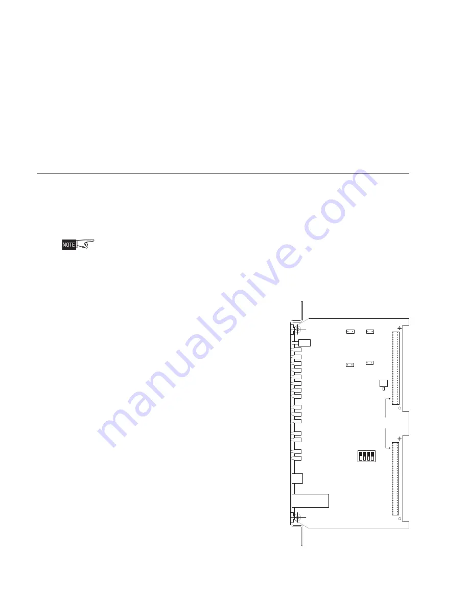
The following components must be set prior to inserting the card into the CC-5 (refer
to Figure 2):
S1, Ground Fault Detection Control:
Press the lever down to enable ground fault
detection. Move the lever to the up position to disable ground fault detection. (Refer
to Figure 2.)
It is recommended to enable ground fault detection on ONLY one NIC-C in the system.
(One for HNET and if used, one for XNET.) If multiple NIC-Cs have ground fault detection
enabled, multiple troubles will be reported to the PMI/PMI-2/PMI-3 (XLS), FCM2041-U2
(Desigo Fire Safety Modular), FCM2041-U3 (Cerberus PRO Modular) when a ground
fault is present. In all cases at least one NIC-C must have ground fault detection
enabled.
S3, NIC-C Options:
Position 1: Network Selection -
Set this switch to the ON
position for HNET. Set to the OFF
position for XNET.
Position 2: Network Style -
Set to ON for Class-B/Style 4.
Set to OFF for Class-X/Style 7.
Position 3: CAN Network enable-
Set to ON if CAN network is
used. Set to OFF if CAN network
is not used
Position 4: Future Use -
Set to OFF.
S4, Reset Switch:
Momentarily Closed
switch that when pressed will initiate a hard
reset to the NIC-C (similar to a cold boot).
NCC-2F-HNET-VNT Jumper Settings:
When Class-B/Style 4 wiring is used for an
NCC-2F-HNET-VNT application, remove
jumper P2 except on the NIC-C that is
connected to the NCC-2F card. When Class-
X/Style 7 wiring is used for an NCC-2F-HNET-
VNT application, remove jumpers P2 and P4
except on the NIC-C that is connected to the NCC-2F card.
Figure 2
NIC-C
Switch
Location
96 PIN DIN
PLUG CONNECTOR
S5, S6, S7
S3
S1
S4
On
1
4
3
2
RESET
SWITCH
NETWORK
ADDRESS
NETWORK
PORT
P5
P3
P4
P2


