2
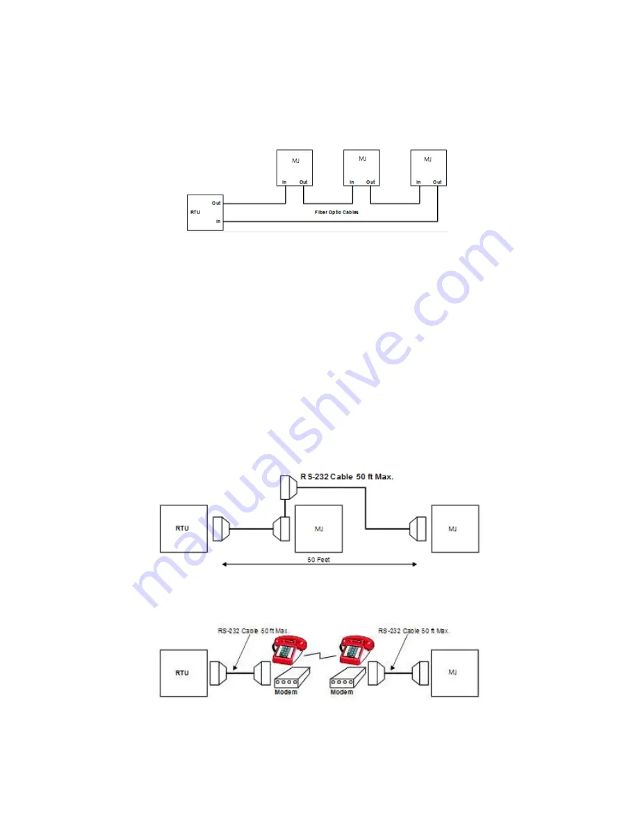
The Fiber Optic interface on the Communications Module uses multi-mode fiber optic cable. The electrical signals
are converted to optical signals by the communication unit. The optical signals are then transmitted via the fiber
optic cable to the RTU. Communications modules in the path between the transmitting communications module and
the RTU act as repeaters and simply regenerate the signals and forward them to the next device as seen in Figure 2-
1.
Figure 2-1: Fiber Optic Network
2.2 Wire Transmission
The advantage of wire transmission is simple installation. The MJ-5 supports two popular wire interfaces: RS-232
and RS-485. The screw terminal block connector supplied with the module can be wired for either interface.
Connection to the supervisory device is typically accomplished using a DB-9 (DE-9) connector for RS-232, while
the connector used for RS-485 will vary with the application.
2.2.1
RS-232
Direct RS-232 connections are limited to a maximum distance of 50 feet, Figure 2-2. The RS-232/485 interface on
the MJ-5 Communications Module supports RS-232 multi-drop configurations.
The distance between devices may be extended with modems, Figure 2-3. Modem connections are either dial-up,
short-haul, or radio-based. Dial-up modems are typically deployed when there is easy access to the telephone
connections, while short-haul modems are useful within a facility where there is access to the wiring. Consider using
a radio modem when laying cable for a land-line modem is impractical.
Figure 2-2: RS-232 Connection
Figure 2-3: Modem Connection


