background image

CC1N7461en
21.08.2018

Building Technologies

7

461

Burner Controls

LFE1...

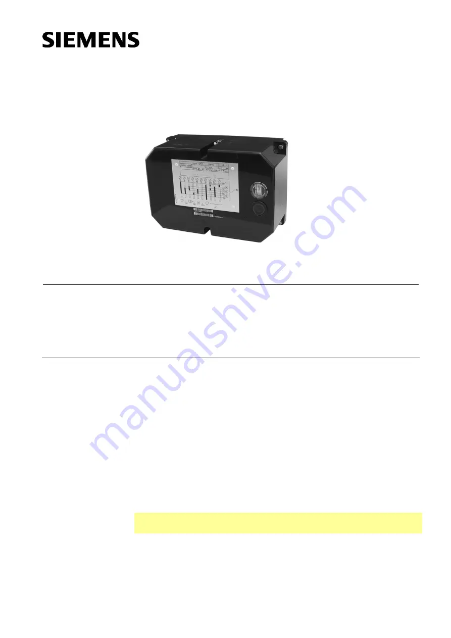
The LFE1... burner control is designed for use with forced draft gas and dual-fuel
burners of any capacity, in intermittent operation.

The LFE1... and this Data Sheet are intended for use by OEMs which integrate the
burner controls in their products.

Use

The LFE1... is designed for the fully automatic control and supervision of single-stage,
multi-stage or modulating gas or dual-fuel burners. It is suited for use with expanding
flame and interrupted pilot type gas burners. Flame supervision is ensured by means of
an ionization probe or a QRA... UV flame detector. Ignition spark proving with a UV
flame detector is also possible. When used in connection with a gas valve proving
system LDU11... (refer to Data Sheet N7696), the control sequence of the LFE1… can
be extended to include automatic gas valve proving. All types of burner controls comply
with the relevant European standards for gas and oil burners of any capacity.

The LFE1... can control the following burner plant components:
fan motor, flue gas fan, air damper, ignition transformer, 1 to 3 fuel valves, load
controller and an external lockout warning device.

·


Applications in accordance with EN 676: Automatic forced draft burners for liquid
fuels

·


Type-tested in accordance with EN 298: 2004

C

Note!
Do not use for new designs.

Summary of Contents for LFE1 Series

Page 1: ...by means of an ionization probe or a QRA UV flame detector Ignition spark proving with a UV flame detector is also possible When used in connection with a gas valve proving system LDU11 refer to Data Sheet N7696 the control sequence of the LFE1 can be extended to include automatic gas valve proving All types of burner controls comply with the relevant European standards for gas and oil burners of ...

Page 2: ...es mounting installation and service work etc must be performed by qualified staff Before making any wiring changes in the connection area of the burner control completely isolate the burner control from the mains supply all polar disconnection Ensure that the plant cannot be inadvertently switched on again and that it is indeed dead If not disconnected there is a risk of electric shock hazard Ens...

Page 3: ... and the ionization probe such that the ignition spark cannot arc over to the ionization probe risk of electrical overloads and that it cannot adversely affect the supervision of ionization Insulation resistance Must be a minimum of 50 MW between ionization probe and ground Soiled detector holders reduce the insulation resistance thus supporting creepage currents Earth the burner in compliance wit...

Page 4: ...ISO 9001 2015 ISO 14001 2015 OHSAS 18001 2007 China RoHS Hazardous substances table http www siemens com download A6V10883536 Lifecycle Burner controls has a designed lifetime of 250 000 burner startup cycles which under normal operating conditions in heating mode correspond to 10 years of usage starting from the production date given on the type field This lifetime is based on the endurance tests...

Page 5: ...in test circuit of burner control The burner control is secured to its base with 4 screws The unit cover is protected against tampering by means of 2 sealing screws refer to Dimensions Printed circuit board with electronic components Large connection area Made of black impact proof and heat resistant plastic Lockout reset button with viewing window for the lockout warning lamp Transparent viewing ...

Page 6: ...E1 8892 LFE1 8892 50 Hz 60 s 5 s 5 s The marking is given inside housing in the range of the contacts Accessories must be ordered separately Flame detectors Photocell detectors RAR9 See Data Sheet N7713 UV flame detectors QRA2 See Data Sheet N7712 UV flame detectors QRA10 See Data Sheet N7712 UV flame detectors QRA4 See Data Sheet N7711 Ionization probe Supplied by thirds Plug in base Plug in base...

Page 7: ...ture range 50 60 C Humidity 95 r h Operation DIN EN 60721 3 3 Climatic conditions class 3K5 Mechanical conditions class 3M2 Temperature range 20 60 C Humidity 95 r h Installation altitude Max 2 000 m above sea level Attention Condensation formation of ice and ingress of water are not permitted If not observed the safety functions are no longer ensured and there will be a risk of electric shock Ion...

Page 8: ... no self checking while measurements are made Ionization probe Flame detector QRA LFE1 14 M C ION QRA For detector currents refer to Technical data C Electrolytic capacitor 100 470 µF DC 10 25 V ION Ionization probe M Microammeter Ri max 5000 W Detector current measurement Legend ...

Page 9: ...h starts running again and continues with the burner s program sequence which can no longer be influenced from externally Preignition 3 seconds 1 5 seconds with the LFE1 1 Release of the first fuel value at terminal 5 the fuel valve of a pilot burner which must be shut on completion of the second safety time must be connected to terminal 10 Completion of the set safety time If no flame is establis...

Page 10: ...will return to its start position In that case the only burner plant component that is switched on is the fan motor connected to terminal 17 Since in normal circumstances the control thermostat or pressurestat continues to call for heat the burner control immediately triggers a new start when the start position is reached Program indicator The program indicator continuously indicates the progress ...

Page 11: ...cts d NTC Delay element negative temperature coefficient e Thermal overload contact OV Oil valve EK1 Lockout reset button on the burner control QRA UV flame detector EK2 Remote lockout reset button R R1 Control thermostat or pressurestat ION Ionization probe R2 Load controller FR Flame relay with contacts fr RV Control valve FW Flame supervision SB Safety limiter GP Gas pressure switch SM Synchron...

Page 12: ... burner on startup with ignition spark supervision t3 3 s 1 5 s Preignition time safety time for ignition spark supervision t4 11 s 5 5 s Interval between release of the first and second fuel valve t5 12 s 6 s Interval between release of the second and third fuel valve or load controller t6 T 30 t1 T 15 t1 Postpurge time t7 3 s 1 5 s Delay time t8 t1 30 t11 t12 t1 15 t11 t12 Duration of startup se...

Page 13: ...curing screw of the red cam N8 Turn camshaft manually until the required prepurge time appears next to the index mark stamped on the sequence switch bracket Hold camshaft firmly and rotate cam N8 until the contact stud actuated by it jumps out or until the cam runs against the stud Tighten the cam securing screw carefully and then check the adjusted time for accuracy The adjustable time is also vi...

Page 14: ...1 N2 N3 7761p07 1296 Cam N2 adjusted to LFE1 LFE1 1 cam N1 time mark I TSA 0 s 0 s II 4 5 s 2 3 s III 9 s 4 5 s Factory setting Depending on variant 2 s Operation with ignition spark supervision Loosen the securing screws of N2 and N3 Hold cam N1 firmly set the setting mark of cam N2 to the time mark I of cam N1 and secure cam N2 Hold cam N2 firmly set the setting mark of cam N3 to the desired tim...

Page 15: ...2 GV3 d1 d1 7461a03 0207 Luft Gas M LK GV3 GV2 GV1 7461a04 1196 A B C D E 22 21 21 d1 18 c1 d1 20 LK a LK z t11 t1 t12 t11 tn t6 t12 7461a05 0301 Air damper control detailed Attention In the case of burners with no air damper or with an air damper not controlled by the burner control terminals 20 21 and 22 must be interconnected and circuit path 18 c1 21 becomes obsolete L2 A B C D E F G H I K L t...

Page 16: ...rating switch BS I Nominal load II Stop III Part load IV Automatic control Gas Luft Gas M GV3 GV2 LK GV 7461a08 1196 A B C DE 21 d1 BS R2 21 d1 22 c1 18 c1 20 a kl Fl z t11 t1 t12 t11 7461a09 1196 Air damper control detailed M1 M2 LK Z GV GV2 GV3 FW L2 Kl 3 17 22 21 6 10 7 11 13 14 13 15 12 A t8 B tn C t6 D E F G H I t6 K L t7 t11 t1 t12 TSA t3 t4 t5 t9 t7 t1 TSA t3 t4 t5 t9 7461a10 0301 A Start G...

Page 17: ... III 1 2 11 12 3 6 T W T c1 LK SQ BS1 I II III IV R2 T d1 GV3 OV3 SB N Mp L2 LF EK2 c1 c2 e1 e2 c1 c2 P LP BS2 GP P R1 21 6 5 10 7 11 M1 M c1 e1 P R M2 M c2 e2 H 1 2 12 13 15 14 16 17 3 19 4 8 18 9 22 20 7461a11 0901 I II III When using UV flame detector QRA terminal 13 must be connected to earth Öl Luft Gas M OV1 OV2 OV3 LK GV1 GV2 GV3 7461a12 1196 Operating switch BS1 I Nominal load II Stop III ...

Page 18: ... QRA terminal 13 must be connected to earth Operating switch BS I Nominal load II Stop III Part load IV Automatic control 17 3 4 8 9 18 19 e M M c max 5A LP P R T W T 0 1A N Mp 7461a15 1196 The air pressure is constantly monitored from burner start to controlled shutdown If the set minimum air pressure is not reached 10 seconds after the start of prepurging 7 seconds with the program with pre and ...

Page 19: ...1m01e 1101 LFE1 Pg entry gland AGG 41041713 FE Metric entry gland AGG 13 1 Pg entry gland AGG 41041713 FE Metric entry gland AGG13 1 Attention To remove the burner control from its plug in base loosen the 4 screws A To remove the unit cover loosen the 2 screws B also C elongated holes for securing the base EK lockout reset button SG viewing window ã 2018 Siemens AG Building Technologies Berliner R...

Reviews: