3
Chapter 1
Introduction
Parts illustration
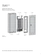
Figure 1.2 below shows the front
view of P1 panel with i-3 Control
Technology V2 components.
Figure 1.2
Panel Overview Diagram
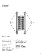
Box (can)
Data rail
BQD breaker
SIPOD
Neutral lugs
Class 2 wire barrier
Neutral extension
Mounting hole (4X)
Location of Main breaker
or main lugs
Ribbon cable
Ground bar
Controller
Note:
Neutral lugs will be covered by the
SIPODs and should not be used (SIPODs
may be added later covering access to the
connections. Connect neutral wires to the
neutral Extensions.

