40
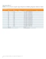
Appendix C
Modbus Coils, Discrete Inputs, Input Registers & Holding Registers Address Tables
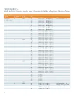
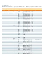
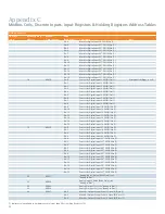
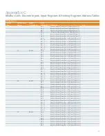
Holding Registers
Function code
Modbus base 0
address
Modbus
5 digit address
Value
(Read/Write*)
Description
Note
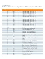
2059
42060
I/O Map for Digital Input 12
2060
42061
I/O Map for Digital Input 13
2061
42062
I/O Map for Digital Input 14
2062
42063
I/O Map for Digital Input 15
2063
42064
I/O Map for Digital Input 16
2064
42065
I/O Map for Digital Input 17
2065
42066
I/O Map for Digital Input 18
2066
42067
I/O Map for Digital Input 19
2067
42068
I/O Map for Digital Input 20
2068
42069
I/O Map for Digital Input 21
2069
42070
I/O Map for Digital Input 22*
2070
42071
I/O Map for Digital Input 23*
2071
42072
I/O Map for Digital Input 24*
2072
42073
I/O Map for Digital Input 25*
2073
42074
I/O Map for Digital Input 26*
2074
42075
I/O Map for Digital Input 27*
2075
42076
I/O Map for Digital Input 28*
2076
42077
I/O Map for Digital Input 29*
2077
42078
I/O Map for Digital Input 30*
2078
42079
I/O Map for Digital Input 31*
2079
42080
I/O Map for Digital Input 32*
2080
42081
/O Map for Analog Input 1
2081
42082
I/O Map for Analog Input 2
2082-2303
… Reserved
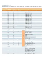
2304
42305
Byte 1
I/O Controller Status
Byte 2
I/O Controller Firmware Version
2305
42306
Minutes since IO Controller
started (rolls over to 0 at 65000)
2306
42307
Milliseconds since IO Controller
started (rolls over to 0 at 60000)
2307
42308
Reserved
2308
42309
Reserved
2309
42310
Reserved
2310
42311
Number of garbled messages since
IO Controller started
2311
42312
Byte 1
Maximum SIPOD opens allowed per minute
Byte 2
Maximum time between SIPOD opens
2312
42313 Byte
1
Maximum SIPOD closes allowed per minute
Byte 2
Minimum time between SIPOD closes
2313
42314
Byte 1
Pulse width for opening a SIPOD
Byte 2
Completion time allowed for a SIPOD open
2314
42315
Byte 1
Pulse width for closing a SIPOD
Byte 2
Completion time allowed for a SIPOD close
2315
42316 Reserved
2316-2559
… Reserved
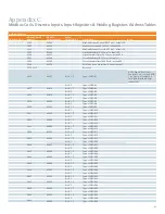
2560
42561
NOTE: This set of parameters are only
written to the POD; when these registers
are read, they represent only the values
temporarily stored on the IO Board. If you
wish to retrieve the parameters from the
PODs, use the “POD Reports”. POD
Number (1 – 42) (must be set fi rst or at
the same time as other parameters)
2561
42562
MaxOpensPerMinute (0-255) – default 255
IO Board Repor
t
Summary of Contents for i-3
Page 1: ...3 User Guide www usa siemens com i 3 i 3 V2 I O Controller Modbus ...
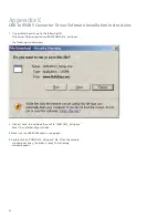
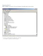
Page 54: ...52 Appendix E USB to RS485 Converter Driver Software Installation Instructions ...
Page 57: ...55 Appendix F Recommended Input Devices ...
Page 58: ...56 Appendix F Recommended Input Devices ...
Page 59: ...57 Appendix F Recommended Input Devices ...
Page 60: ...58 Appendix F Recommended Input Devices ...
Page 61: ...59 Appendix F Recommended Input Devices ...
Page 62: ...60 Appendix F Recommended Input Devices ...
Page 63: ...61 Appendix F Recommended Input Devices ...
Page 64: ...62 Appendix F Recommended Input Devices ...
Page 65: ...63 Appendix F Recommended Input Devices ...
Page 66: ...64 Appendix F Recommended Input Devices ...
Page 67: ...65 Appendix F Recommended Input Devices ...
Page 68: ...66 Appendix F Recommended Input Devices ...
Page 69: ...67 Appendix F Recommended Input Devices ...
Page 70: ...68 Appendix F Recommended Input Devices ...
Page 71: ...69 Appendix F Recommended Input Devices ...
Page 72: ...70 Appendix F Recommended Input Devices ...
Page 73: ...71 Appendix F Recommended Input Devices ...
Page 74: ...72 Appendix F Recommended Input Devices ...
Page 75: ...73 Appendix G Common Networking Setups ...
Page 76: ...74 Appendix G Common Networking Setups ...
Page 78: ...76 Notes ...
Page 79: ......

