background image

Mounting and installation of the compact control panels
Module bus cards

5

182 | 354
Building Technologies

008851_s_en_--

Fire Safety

2016-01-27

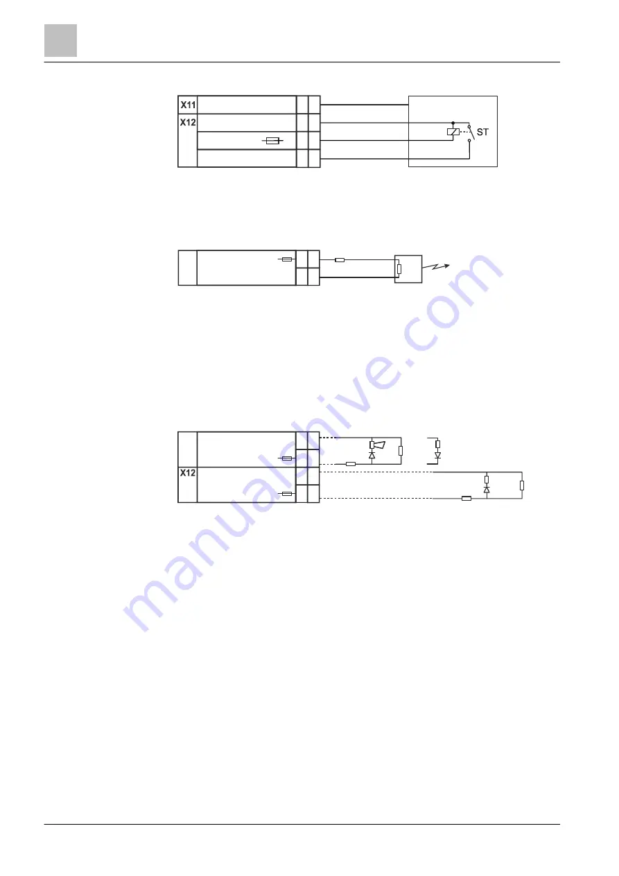
Switching for RE response in accordance with ↑ VdS

Figure 93: Switching for RE response in accordance with VdS

ST

Fault contact of the transmission device

Switching for monitored remote transmission

Figure 94: Switching for monitored remote transmission

Rload  Load resistance
Rcable Line resistance
1

Remote transmission

Switching variants for monitored alarm and horn outputs with

decoupled load (EN 54)

Figure 95: Switching examples for monitored alarm and horn outputs with decoupled load (EN 54)

Rload

Load resistance

Rcable  Line 

resistance

Reol

Termination resistor

1

Standard EOL

2

EOL with decoupled load

5

Fire

0V

27V2

-

+

1

4

UE _Rückmeldung

+

7

5

6

U

+

-

X11

UE_Fault-

1

Rload

Rcable

Rload

+

-

5

6

FireOutput2-

Fire

+

-

7

8

FireOutput1-

Fire

X11

Rcable

Reol

Example horn output

Example alarm output

Reol

Rcable

1

2

Rload

Summary of Contents for FS20

Page 1: ...FS20 Fire detection system Mounting Installation MP6 008851_s_en_ Building Technologies 2016 01 27 Control Products and Systems ...

Page 2: ... communication thereof to others without express authorization are prohibited Offenders will be held liable for payment of damages All rights created by patent grant or registration of a utility model or design patent are reserved Issued by Siemens Switzerland Ltd Building Technologies Division International Headquarters Gubelstrasse 22 CH 6301 Zug Tel 41 41 724 2424 www siemens com buildingtechno...

Page 3: ...housing 28 3 2 6 Mounting material 30 3 3 Rear panels version CH 31 3 3 1 Eco rear panel of the FT2040 CZ 31 3 3 2 Standard rear panel for FC2020 CZ 32 3 3 3 Comfort rear panel of the FC2020 CC 33 3 3 4 Comfort rear panel of the FC2030 CC 35 3 3 5 Comfort rear panel of the FC2040 CC 37 3 4 Operating unit operating add on and cover cap packaging unit 39 3 4 1 Operating units and operating add on 39...

Page 4: ...y 150 W 98 5 7 1 Installation 98 5 7 2 Fitting an additional power supply 150 W 101 5 7 3 Pin assignments version A4 103 5 7 4 Pin assignments version A5 106 5 8 Battery kit 9 V FR 113 5 8 1 Installation in the Eco and Standard housings 113 5 8 2 Installation in Comfort housing 114 5 8 3 Pin assignments 114 5 9 Shield connection terminal blocks DE 115 5 10 Loop extension 116 5 10 1 Installation 11...

Page 5: ...tallation 185 5 20 2 Pin assignments 187 5 21 Event printer 189 5 21 1 Installation 189 5 21 2 Pin assignments 191 5 22 Key switch Kaba FTO2005 C1 194 5 23 Redux module DE 195 5 23 1 Installation 195 5 23 2 Pin assignments 196 5 24 Input output module FDCIO224 DE 197 5 24 1 Installation 197 5 25 Sounder module 198 5 25 1 Installation 198 5 25 2 Pin assignments 199 5 26 Modes of mounting for module...

Page 6: ...llation checklist 260 6 Mounting and installation FC2080 262 6 1 Mounting procedure 262 6 2 Processor unit 19 FC2080 264 6 2 1 Installation 265 6 2 2 View of card cage CPU FCC2003 A1 266 6 2 3 Pin assignments 268 6 3 Assembling the carrier 19 card cage 271 6 3 1 Installing the card cage 5 slots on the carrier 19 card cage 272 6 3 2 Installing DIN rails on the carrier 19 card cage 273 6 4 Installin...

Page 7: ...ard 320 6 15 Installing the fiber optic cable network module 322 6 15 1 Installation 322 6 16 Installing an Ethernet switch MM FN2008 323 6 16 1 Installation 323 6 17 Installing an Ethernet switch modular FN2012 324 6 17 1 FHA2029 in the housing 19 pedestal housing 324 6 17 2 FN2012 in station with housing 19 pedestal housing 325 6 18 Installing the battery kit 9 V FR 326 6 18 1 Installation 326 6...

Page 8: ...Building Technologies 008851_s_en_ Fire Safety 2016 01 27 8 354 ...

Page 9: ...nformation on country specific components Country specific components are marked with square brackets e g DE It may be the case that these cannot be used in your country Target groups The information in this document is intended for the following target groups Target group Activity Qualification Installation personnel Assembles and installs the product components at the place of installation Carri...

Page 10: ...f international standard ISO 8601 format YYYY MM DD Conventions for text marking Markups Special markups are shown in this document as follows Requirement for a behavior instruction 1 2 Behavior instruction with at least two operation sequences Version option or detailed information for a behavior instruction Intermediate result of a behavior instruction End result of a behavior instruction Number...

Page 11: ...l manual FG2020 1 2 Download center You can download various types of documents such as data sheets installation instructions and license texts via the following Internet address http siemens com bt download l Enter the document ID in the Find by keyword input box You will also find information about search variants and links to mobile applications apps for various systems on the home page 1 3 Tec...

Page 12: ...ter Installing mounting kits adapted for FN2008 and FN2009 Referenced documents updated Chapter Mounting and installation of fire terminal Touch Mounting of mains filter removed mounting of desktop housing FT2080 modified installation in wall housing changed to housing Standard Chapter Insert license key updated Notice about ground fault monitoring incorporated into chapter Mounting and installati...

Page 13: ...fied FC2080 Key safe adapter chapter on wiring with FDCIO222 added and wiring via I O card programmable changed heating isolation integrated Various minor corrections and adaptations CPR replaces CPD The Construction Products Regulation CPR 305 2011 replaces the previous Construction Products Directive CPD 89 106 o 05 2012 Edition MP EN 4 0 Fire control panel FC2080 Housing 19 pedestal cabinet FH2...

Page 14: ...Fourth edition MP2 1 Operating add on FCM2008 N1 modified adjustment elements i 11 2008 Third edition MP2 1 Various corrections 150 W supply horizontal Card cage mounting Module bus card pin assignment h 08 2008 Second edition MP2 1 for field test Various corrections and additions g 2008 05 First edition MP2 1 for VdS New MP2 1 components Minor changes f 2007 12 Fourth corrected and extended editi...

Page 15: ... dangers the type of danger or possible consequences measures and prohibitions examples of which are shown in the following table General danger Explosive atmosphere Voltage electric shock Laser light Battery Heat Signal word The signal word classifies the danger as defined in the following table Signal word Danger level DANGER DANGER identifies a dangerous situation which will result directly in ...

Page 16: ... is shown as follows WARNING Nature and origin of the danger Consequences if the danger occurs Measures prohibitions for danger avoidance How possible damage to property is presented Information about possible damage to property is shown as follows NOTICE Nature and origin of the danger Consequences if the danger occurs Measures prohibitions for danger avoidance ...

Page 17: ...and supervision of a qualified electrician in accordance with the electrotechnical regulations Wherever possible disconnect products from the power supply when carrying out commissioning maintenance or repair work on them Lock volt free areas to prevent them being switched back on again by mistake Label the connection terminals with external external voltage using a DANGER External voltage sign Ro...

Page 18: ...ou must collaborate with the people appointed The activation of fire control installations for test purposes must not cause injury to anyone or damage to the building installations The following instructions must be observed Use the correct potential for activation this is generally the potential of the building installation Only check controls up to the interface relay with blocking option Make s...

Page 19: ...he instructions or the disregard of danger warnings contained in the documentation This applies in particular to the following damage Personal injuries or damage to property caused by improper use and incorrect application Personal injuries or damage to property caused by disregarding safety instructions in the documentation or on the product Personal injury or damage to property caused by poor ma...

Page 20: ...e you plan and or configure a fire detection installation Read the Release Notes before you carry out a firmware update to a fire detection installation NOTICE Incorrect planning and or configuration Important standards and specifications are not satisfied Fire detection installation is not accepted for commissioning Additional expense resulting from necessary new planning and or configuration Rea...

Page 21: ...add on with cover cap Options When unpacking the station do not damage or dispose of the packaging The packaging includes a drilling template for the corresponding station housing The packaging of the rear panel can be used as protection after mounting to protect the open station against soiling and damage 3 2 Station rear panels packaging unit The following chapters show views of the stations as ...

Page 22: ...lable in the Eco housing Figure 1 Fire terminal in Eco rear panel 1 Eco rear panel 2 Opening for cable feed from rear side 3 DIN rail for disconnect terminal blocks 4 Fastening tabs for the cover cap 5 Hole for wall mounting top 6 Recesses for the hinges of the operating unit 7 Mounting holes for operating unit 8 Fire terminal board 9 Holes for wall mounting bottom 6 7 8 9 7 7 9 7 6 1 2 3 4 2 5 ...

Page 23: ...ard rear panel 2 Hole for wall mounting top 3 Fastening tabs for the cover cap 4 Openings for cable feed from rear side 5 Recesses for the hinges of the operating unit 6 Mounting holes for operating unit 7 Periphery board 2 loop 8 Holes for wall mounting bottom 9 Secondary side cabling of the power supply 10 Primary side cabling of the power supply 11 Power supply 12 DIN rail with network separati...

Page 24: ... panels FC2020 and FC2040 in the Comfort housing is identical One exception is the fire control panel FC2040 BB SE FI which is supplied in the Large housing Example of a fire control panel FC2040 in Comfort rear panel 1 Comfort rear panel 2 Holes for wall mounting top 3 DIN rail for additional components 4 Fastening tabs for the cover cap 5 Openings for cable feed from rear side 7 6 8 9 10 1 2 4 5...

Page 25: ...holes for operating unit 8 Periphery board 9 Secondary side cabling of the power supply 10 Recesses for the hinges of the operating add on 11 Mounting holes for the operating add on 12 Power supply 150 W 13 Holes for wall mounting bottom 14 Strain relief for mains supply cable 15 DIN rail with network separation terminals also for additional components 16 Primary side cabling of the power supply ...

Page 26: ...3 Fire control panel FC2030 in Comfort rear panel 1 Comfort rear panel 2 DIN rail for additional components 3 Fastening tabs for the cover cap 4 Openings for cable feed from rear side 5 Holes for wall mounting top 6 Recesses for the hinges of the operating unit 7 Mounting holes for operating unit 8 Periphery board 2 loop 1 2 3 4 5 17 7 7 11 15 11 13 16 14 7 8 10 11 12 11 10 13 7 6 5 5 6 ...

Page 27: ...power supply 10 Recesses for the hinges of the operating add on 11 Mounting holes for the operating add on 12 Power supply 150 W 13 Holes for wall mounting bottom 14 Strain relief for mains supply cable 15 DIN rail with network separation terminals and for additional components 16 Primary side cabling of the power supply unit 17 Card cage 2 slots for modernization cards ...

Page 28: ...etup in the Large housing Figure 4 Fire control panel in Large rear panel 1 Large rear panel 2 Holes for wall mounting top 3 Fastening tabs for the cover cap 4 Openings for cable feed from rear side 5 Recesses for the hinges of the operating unit 6 Mounting holes for operating unit 7 Periphery board 4 loops 8 Secondary side cabling of the power supply 6 5 6 7 8 9 10 1 2 3 4 2 6 5 11 10 9 12 13 18 ...

Page 29: ...mounting bottom 14 Primary side cabling of the power supply 15 DIN rail with network separation terminals and for additional components 16 Strain relief for mains supply cable 17 Card cage 5 slots for module bus cards 18 Mounting plate with slots for fastening the shield connection terminal blocks 1 1 The mounting plate as a carrier for the periphery board and the card cage is offset around 2 cm f...

Page 30: ... batteries 1 2k2 500 mW resistance 3 3k01 500 mW resistance 3 1 kV 1 A diodes 1 There are three extra screws with the Eco and Standard housings 2 Both M3 12 screws are required for cable strain relief if a thick supply cable is used 3 The installation plate must be affixed to the outside of the control panel housing and must be clearly legible EN 54 2 The installation number and the date of commis...

Page 31: ...s for Switzerland CH 3 3 1 Eco rear panel of the FT2040 CZ Figure 5 Fire terminal FT2040 CZ in Eco housing 1 Eco rear panel 2 DIN rail L 70 mm 3 Fastening tabs for the cover cap 4 Hole for wall mounting top 5 Opening for cable feed from rear side 6 Recesses for the hinges of the operating unit 7 Mounting holes for operating unit 8 Terminal set on DIN rail L 70 mm 9 Fire terminal board 10 Holes for...

Page 32: ...ing tabs for the cover cap 4 Openings for cable feed from rear side 5 Recesses for the hinges of the operating unit 6 Mounting holes for operating unit 7 Periphery board 2 loop 8 Holes for wall mounting bottom 9 Secondary side cabling of the power supply 10 Primary side cabling of the power supply 11 Power supply 70 W 12 DIN rail L 180 mm with mains separation terminals relay module and blocking m...

Page 33: ...anel FC2020 CC in Comfort rear panel 1 Comfort rear panel 2 Holes for wall mounting top 3 DIN rail for additional components 4 Fastening tabs for the cover cap 5 Openings for cable feed from rear side 6 Recesses for the hinges of the operating unit 7 Mounting holes for operating unit 8 DIN rail L 420 mm with terminal set 15 6 7 8 9 10 1 2 3 5 7 17 18 12 16 12 14 7 6 11 12 13 12 11 14 2 7 4 ...

Page 34: ...oop 10 Cable duct L 410 mm 11 Recesses for the hinges of the operating add on 12 Mounting holes for the operating add on 13 Power supply 70 W 14 Holes for wall mounting bottom 15 Strain relief for mains supply cable 16 DIN rail L 175 mm with mains separation terminal and socket type 13 17 DIN rail L 320 mm with terminal set 18 Cable duct L 300 mm ...

Page 35: ...l 1 Comfort rear panel FHA2003 A1 2 Holes for wall mounting top 3 DIN rail L 420 mm with terminal blocks and fuses 4 DIN rail L 175 mm with 3 mains input terminals 5 Fastening tabs for the cover cap 6 Terminal block switch module and 2 fuses for secondary supply 7 Openings for cable feed from rear side 8 Recesses for the hinges of the operating unit 2 3 5 7 1 2 8 9 11 13 9 8 14 13 15 12 12 9 15 13...

Page 36: ...l pipes 11 Periphery board 2 loops FCI2002 A1 12 Recesses for the hinges of the operating add on 13 Mounting holes for the operating add on 14 Power supply 150 W mounted on DIN rail L 175 mm 15 Holes for wall mounting bottom 16 Strain relief for mains supply cable 17 DIN rail L 175 mm with 7 mains separator terminals and socket type 13 18 Card cage 2 slots FCA2007 A1 19 I O module FDCIO222 ...

Page 37: ...anel FC2040 CC in Comfort rear panel 1 Comfort rear panel 2 Holes for wall mounting top 3 DIN rail for additional components 4 Fastening tabs for the cover cap 5 Openings for cable feed from rear side 6 Recesses for the hinges of the operating unit 7 Mounting holes for operating unit 8 DIN rail L 420 mm with terminal set 1 2 5 2 14 7 7 17 16 11 15 11 13 18 6 7 8 9 7 6 10 11 12 11 10 13 3 4 ...

Page 38: ...esses for the hinges of the operating add on 11 Mounting holes for the operating add on 12 Power supply 150 W mounted on DIN rail 13 Holes for wall mounting bottom 14 Strain relief for mains supply cable 15 DIN rail L 175 mm with mains separation terminal and socket type 13 16 Cable duct L 300 mm 17 DIN rail L 320 mm with terminal set 18 Cable duct L 410 mm ...

Page 39: ...e operating unit is installed in the upper section of the housing The operating add on is installed either in the bottom part of the Comfort or Large housing or in an additional empty housing In the operating units MP3 0 uses the PMI mainboard FCM2004 and also the PMI mainboard FCM2027 You will find detailed information about this in document 008837 Figure 10 Rear view of operating unit without op...

Page 40: ... securing the operating unit 2x M2 5 screws for securing the hinge of the operating unit 1x ribbon cable for the connection from the PMI mainboard to the periphery board Inscription set or inscription sheet only for operating unit You will find additional inscription strips e g for the operating add on in document 009026 3 4 2 Cover cap Figure 12 Rear view of cover cap 1 Distance pins 2 Fixing scr...

Page 41: ... packaging units The figures show the maximum possible scope of equipment You will find detailed information about the individual components in document 008837 3 5 1 Eco housing fire terminal The fire terminal is available in the Eco housing Figure 13 Components in the Eco housing fire terminal 1 Battery kit 9 V FR option 2 Power supply 70 W option 3 Mains separation terminals or relays on DIN rai...

Page 42: ...ls The fire control panel FC2020 2 loop is available in the Standard housing Figure 14 Components in the Standard housing fire control panel 1 Battery kit 9 V FR option 2 Power supply 70 W 3 Relay option on DIN rail 4 Shield connection terminal blocks DE or cable kit communication options 5 Loop extension FDnet option 6 Periphery board 2 loop 7 Batteries 6 1 2 3 5 4 ...

Page 43: ...is identical One exception is fire control panel FC2040 BB FI SE which is supplied in the Large housing Figure 15 Components in the Comfort housing taking the example of fire control panel FC2040 with cascaded power supply 1 Batteries 2 Socket option on DIN rail 3 Battery kit 9 V FR option 4 Space for other options e g fire brigade periphery module DE or card cage 2 slots with the FC2030 5 Shield ...

Page 44: ...uilding Technologies 008851_s_en_ Fire Safety 2016 01 27 7 Loop extensions FDnet option 8 Periphery board 4 loop with FC2040 and or periphery board 2 loop with FC2020 and FC2030 9 Power supply 150 W fitted horizontally as standard 10 Additional power supply 150 W option ...

Page 45: ...l panel FC2060 with power supply switched in parallel 1 Relay module option on DIN rail 2 Socket option on DIN rail 3 Card cage 5 plug in cards not in the FC2040 BB 4 Module bus cards max 5 items in card cage not in the FC2040 BB 5 Shield connection terminal blocks DE or cable kit communication on mounting plate options 6 Mounting plate for card cage 5 slots and periphery board 4 loop 7 Loop exten...

Page 46: ...re 18 Components on the operating unit with PMI mainboard FCM2027 1 PMI mainboard 2 Space for options printer or LED indicator 3 Network module SAFEDLINK on X13 master module option 4 Slot 1 SER_OPT1 for the first serial module at X14 option 5 Slot 2 SER_OPT2 for the second serial module at X19 option 6 Degraded mode network module SAFEDLINK on X12 option 7 Connection module card cage on X11 stand...

Page 47: ...es for extended networking 3 5 6 1 Modules in station with Comfort housing Installation arrangement of an Ethernet switch MM FN2008 A1 or Security module firewall FN2009 A1 taking the example of the FC2040 AA with fire brigade periphery module FCI2001 D1 1 Mounting kit switch Comf installation bracket with two DIN rails 2 FN2008 A1 or FN2009 A1 1 2 ...

Page 48: ...2009 A1 can be installed in a fire control panel FC2020 An additional empty housing Eco or Standard is needed for this application and is fitted under the fire terminal NOTICE Protection from battery leakage The cable connections into the bottom housing must be led through a packed gland to ensure protection from battery leakage Figure 19 Example of module arrangement with fire control panel in th...

Page 49: ... components 3 49 354 Building Technologies 008851_s_en_ Fire Safety 2016 01 27 1 Housing Eco FH2001 A1 empty 2 Mounting kit switch Comf mounting bracket with two DIN rails 3 FN2008 A1 or FN2009 A1 4 Fire control panel FC2020 in the housing Standard ...

Page 50: ...dule firewall FN2009 A1 can be installed in the fire terminal FT2040 An additional empty housing Eco is needed for this application and is fitted under the fire terminal NOTICE Protection from battery leakage The cable connections into the bottom housing must be led through a packed gland to ensure protection from battery leakage Figure 20 Sample structure of fire terminal with FN2008 A1 or FN2009...

Page 51: ... 51 354 Building Technologies 008851_s_en_ Fire Safety 2016 01 27 1 Housing Eco FH2001 A1 empty 2 Installation kit switch comf 3 I O module for alarming the detector contact 4 FN2008 A1 or FN2009 A1 5 FT2040 fire terminal with optional power supply and batteries ...

Page 52: ...h 10 screws M4 x 6 2 cable ducts 80 x 80 x 80 x 1500 mm 12 Philips screws M6 x 10 2 toothed discs M6 10 shield connection terminal blocks 1 switch 1 power socket Euro 4 expansion bolts with screws for wall mounting 1 Siemens Sinteso sticker each 4 screws to fix the cabinet on the base Components Each component is a packaging unit Battery tray FC2080 Basic components Processor unit 19 FC2080 incl p...

Page 53: ...en_ Fire Safety 2016 01 27 4 2 Location of components Figure 21 FC2080 location of components 1 Housing 19 free standing cabinet with base 2 Carrier 19 power supply with two power supplies 150 W 3 Power supply kit 150 W A 4 Battery tray 19 with batteries 5 Processor unit 19 FC2080 ...

Page 54: ... in the highest possible position Battery tray 19 with batteries must be installed in the lowest possible position B Second power supply group with carrier 19 power supply and battery tray 19 with batteries Carrier 19 power supply must be installed directly below the first carrier Battery tray 19 with batteries must be installed above the first battery tray C Processor unit 19 FC2080 must be insta...

Page 55: ...t and the maximum number of card cages view of the left hand side wall and view from the front 1 FC2080 view of rear panel 2 Processor unit 19 FC2080 3 Carrier 19 card cage with two card cages 5 slots 4 Second carrier 19 card cage with two card cages 5 slots 5 Third carrier 19 card cage with two card cages 5 slots 6 Carrier 19 optional with installed fiber optic cable network module 7 Battery tray...

Page 56: ...t hand side wall 4 4 Setup with two power supply groups sample FC2080 with two carriers 19 power supply and two battery groups Figure 23 FC2080 with the maximum number of batteries view of the left hand side wall and view from the front 1 FC2080 view of rear panel 2 Processor unit 19 FC2080 3 Carrier 19 card cage with two card cages 5 slots 4 Second carrier 19 card cage with two card cages 5 slots...

Page 57: ...afety 2016 01 27 5 Carrier 19 optional with installed fiber optic cable network module 6 Top battery tray 19 with batteries 7 Bottom battery tray 19 with batteries 8 Base 9 Grounding terminal 10 Carrier 11 Bottom carrier 19 power supply 12 Top carrier 19 power supply 13 FC2080 view of the left hand side wall ...

Page 58: ...g add ons Operating units and their operating add ons are separate stations if observed functionally and can be installed in the door of the FC2080 as an option Figure 24 FC2080 with optional operating unit view of the inside of the cabinet door 1 Operating unit option 2 Operating add on option 3 Breakout opening for second operating add on 4 Plan compartment A3 1 2 3 4 ...

Page 59: ... mains supply cable is disconnected from the power supply Check to make sure that the mains is secured against inadvertently being switched on Always connect the grounding PE to the mains supply cable first The components must be installed by a qualified electrician or a trained person NOTICE Damage to hardware Perform all mechanical work before installing the components Insert possible plug in ca...

Page 60: ...on plate on the outside of the control panel housing such that it is clearly legible Add the site number No and the commissioning date Date during commissioning in accordance with EN 54 2 a The station is then ready for commissioning Figure 25 Sample installation plate 85 265VAC 90VAC EN54 2 PSU EN54 4 Prod Date A5Q00017142A 06 FC2020 G209076 Siemens Switzerland Ltd Fire Safety Security Products C...

Page 61: ...ace caused e g by overheating of the batteries Danger of fire If you mount the station on a flammable wall all cut out sections for the mounting holes must be sealed using the supplied aluminium stickers 1 Break out the required cable openings on the rear panel Signal and control cables must be fed into the housing from above or from the rear EMC protection 2 Screw in the cable gland for the mains...

Page 62: ... The additional housings are generally mounted right below the stations and attached to them with screws The housings comprise the following elements Rear panel Operating add on with LED indicators depending on the version Cover cap Figure 26 Mounting additional housing example Standard housing view from the front and view of the additional housing from above 1 Empty additional housing 2 Holes for...

Page 63: ... entries at the bottom of the rear panel and the cover of the additional housing 4 5 as well as the mounting holes for housing assembly 3 2 Attach edge protection strips or rubber grommets to the cable entries 3 Fasten the rear panel of the additional housing 1 in the same way as that of the station Make sure that the alignment is exact 4 Stick the supplied aluminium stickers over all holes for wa...

Page 64: ...into the housing on the right from above or from the rear Batteries must be installed so that they cannot leak No cable openings should be made in the base of the housing unless an additional housing is mounted below the station to accommodate the batteries Figure 27 Laying the mains cable for the Standard housing left and the Comfort housing right 1 EMC critical zone no high voltage power permitt...

Page 65: ... sure that the cable is current free Ensure that the mains is secured against inadvertently being switched on Installation 1 Lay the mains cable 5 along the left side of the housing 2 Insulate the mains cable as needed and connect it to the disconnect terminals 3 according to the pin assignment specified in the next chapter Use cable end sleeves for wires 3 Fix the cable with the strain relief cla...

Page 66: ...housing left and the Comfort housing right 1 Mains cable feed from above 2 Strain relief clamp 3 Ground on the rear panel 4 Disconnect terminal 5 Primary cabling for power supply 6 Ground cable yellow green pre assembled 7 Cable tie PE Protective conductor terminal on the left N Neutral conductor terminal in the middle L1 External conductor terminal on the right with mains disconnector 2 PE 7 5 6 ...

Page 67: ...n the Standard housing left and the Comfort housing right 1 Mains cable feed from above 2 Strain relief clamp 3 Ground cable yellow green pre assembled 4 Ground on the rear panel 5 Primary cabling for power supply 6 Disconnect terminal 7 Cable fixing with cable tie 8 Cable duct PE Protective conductor connection terminal 7 N Neutral conductor terminal 4 L1 External conductor terminal 1 PE 5 PE N L...

Page 68: ...ed from above 2 Strain relief clamp 3 Ground on the rear panel 4 Disconnect terminal 5 Primary cabling for power supply 6 Ground cable yellow green pre assembled PE Protective conductor connection terminal 2 L1 External conductor terminal 3 N Neutral conductor terminal 4 5 2 4 Installing the operating unit and the operating add on This chapter describes how to assemble the operating units Prerequi...

Page 69: ...ions are installed However the cable routing is the same for all operating units From MP EN 4 0 onwards the operating units are supplied with the PMI mainboard FCM2027 Stations that are equipped with the PMI mainboard FCM2004 must not be integrated in an extended network You will find detailed information about this in product data document 008837 and in the planning document 008843 Figure 31 Moun...

Page 70: ...he operating unit 2 Hinge of the operating unit 3 Screw for securing the hinge Mounting steps 1 From the rear side hang the operating unit by inserting the hinges 2 into the openings in the rear panel of the housing 1 2 Hold the operating unit in place and secure the hinges 2 with the screws 3 3 Insert the connection cable to the periphery board into the respective plug in positions 6 and 9 as sho...

Page 71: ... assembling a station 5 71 354 Building Technologies 008851_s_en_ Fire Safety 2016 01 27 Figure 34 Inserting the inscription strips into the operating unit 1 Inscription LEDs 2 Inscription standard keys 1 3 Inscription standard keys 2 4 Inscription station type 1 2 3 4 ...

Page 72: ...m half of the housing For stations in an Eco or Standard housing operating add ons must be installed in a separate housing Additional operating add ons can be mounted in separate additional housings The mounting is carried out as described for the operating unit Figure 35 Example view of Comfort housing with operating add on 1 Fixing screws left 2 Operating unit 3 Fixing screws right 4 Operating a...

Page 73: ...er wire of the batteries for serial connection should not be inserted The cover cap is hooked into the rear panel with four holder cams and screwed at the top The housings must be opened and closed with an Allen key standard equipment for service technicians Mounting steps 1 Always hook the lower cover cap in first 2 Insert the cover cap at an angle into the guides on the rear panel 3 Secure the t...

Page 74: ...board 2 loop FCI2002 A1 is mounted in the fire control panels in the factory and only has to be replaced in the event of a repair Figure 36 Mounting of periphery board 2 loop 1 Threaded bolts on rear panel 2 9 fixing screws 3 Periphery board 2 loop X1 Connector for supply X3 Connector for connection cable to PMI mainboard operating unit X400 Connector for periphery bus X9 X8 X7 X6 X12 X11 2 3 1 X4...

Page 75: ... remove 5 3 2 Pin assignments Inputs and outputs which are not used do not require termination FDnet detector lines which are not used must not be terminated 5 3 2 1 X1 supply Pin Designation Description 1 BATT Message input from the power supply Battery fault 2 CONV Message input from the power supply Converter fault 3 MAINS Message input from the power supply Mains failure 4 COMMON Ground 5 3SRC...

Page 76: ..._en_ Fire Safety 2016 01 27 5 3 2 2 X6 Horn alarm and fault monitored outputs Pin Designation Description 6 FAU_OUT Output fault 5 VSYS_O Supply output for consumer fault 4 AL_OUT Alarm output 3 AL_OUT Alarm output 2 SOUND1 Horn output 1 SOUND1 Horn output Admissible cable cross section 0 2 1 5 mm 1 Remote transmission ...

Page 77: ... FAU_NC RT fault normally closed contact 5 FAU_COM RT fault center tap common 4 FAU_NO RT fault normally open contact 3 AL_NC RT alarm break contact normally closed 2 AL_COM RT alarm center tap common 1 AL_NO RT alarm make contact normally open Admissible cable cross section 0 2 1 5 mm 1 Remote transmission FAU_ Diagram of relay in normal operation contact 5 4 closed AL_ Diagram of relay in normal...

Page 78: ...puts 1 4 and supply output 1 Pin Designation Description 6 GND_01 Supply output 1 5 VSYS_01 Supply output 1 4 I O4 Configurable input output 4 3 I O3 Configurable input output 3 2 I O2 Configurable input output 2 1 I O1 Configurable input output 1 Admissible cable cross section 0 2 1 5 mm All inputs outputs can be connected as follows 1 Configured as output 2 Configured as input ...

Page 79: ...8 3 I O7 Configurable input output 7 2 I O6 Configurable input output 6 1 I O5 Configurable input output 5 Admissible cable cross section 0 2 1 5 mm All inputs outputs can be connected as follows 1 Configured as output 2 Configured as input 5 3 2 6 X11 detector line loop 1 Pin Designation Description 4 LOOP1_2 Loop 1 stub 2 3 LOOP1_2 Loop 1 stub 2 2 LOOP1_1 Loop 1 stub 1 1 LOOP1_1 Loop 1 stub 1 Ad...

Page 80: ...851_s_en_ Fire Safety 2016 01 27 5 3 2 7 X12 detector line loop 2 Pin Designation Description 4 LOOP2_2 Loop 2 stub 4 3 LOOP2_2 Loop 2 stub 4 2 LOOP2_1 Loop 2 stub 3 1 LOOP2_1 Loop 2 stub 3 Admissible cable cross section 0 2 1 5 mm One loop or two stubs can be connected 3 4 1 2 X12 LOOP2_1 LOOP2_1 LOOP2_2 LOOP2_2 ...

Page 81: ...re control panels in the factory and only has to be replaced in the event of a repair Figure 37 Mounting of the periphery board 4 loops 1 Threaded bolts on rear panel 2 13 fixing screws 3 Periphery board 4 loops X1 Connector for supply X3 Connector for connection cable to PMI mainboard operating unit X400 Connector for the periphery bus to the fire brigade periphery module DE X401 Connector for pe...

Page 82: ...tall any modules that you may have had to remove 5 4 2 Pin assignments Inputs and outputs which are not used do not require termination FDnet detector lines which are not used must not be terminated 5 4 2 1 X1 supply Pin Designation Description 1 BATT Message input from the power supply Battery fault 2 CONV Message input from the power supply Converter fault 3 MAINS Message input from the power su...

Page 83: ...tput 2 3 SOUND2 Horn output 2 2 SOUND1 Horn output 1 1 SOUND1 Horn output 1 Admissible cable cross section 0 2 1 5 mm 5 4 2 3 X6 alarm and fault monitored outputs Pin Designation Description 4 FAU_OUT Output fault 3 VSYS_O Supply output for consumer fault 2 AL_OUT Alarm output 1 AL_OUT Alarm output Admissible cable cross section 0 2 1 5 mm 1 Remote transmission 1 2 X5 SOUND2 SOUND2 F403 3 4 SOUND1...

Page 84: ...6 FAU_NC RT fault normally closed contact 5 FAU_COM RT fault center tap common 4 FAU_NO RT fault normally open contact 3 AL_NC RT alarm break contact normally closed 2 AL_COM RT alarm center tap common 1 AL_NO RT alarm make contact normally open Admissible cable cross section 0 2 1 5 mm 1 Remote transmission FAU_ Diagram of relay in normal operation contact 5 4 closed AL_ Diagram of relay in norma...

Page 85: ...able input output 6 5 I O5 Configurable input output 5 4 I O4 Configurable input output 4 3 I O3 Configurable input output 3 2 I O2 Configurable input output 2 1 I O1 Configurable input output 1 16 GND_02 Supply output 2 15 VSYS_02 Supply output 2 14 I O12 Configurable input output 12 13 I O11 Configurable input output 11 12 I O10 Configurable input output 10 11 I O9 Configurable input output 9 10...

Page 86: ...ption X11 X21 1 4 LOOP1_2 Loop 1 stub 2 Connection 1st Loop Connection 3rd Loop 3 LOOP1_2 Loop 1 stub 2 Connection 1st Loop Connection 3rd Loop 2 LOOP1_1 Loop 1 stub 1 Connection 1st Loop Connection 3rd Loop 1 LOOP1_1 Loop 1 stub 1 Connection 1st Loop Connection 3rd Loop Admissible cable cross section 0 2 1 5 mm 1 Loop number without loop extension The technical term LOOP 1 applies to both loops o...

Page 87: ...tion 2nd Loop Connection 4th Loop 3 LOOP1_2 Loop 1 stub 2 Connection 2nd Loop Connection 4th Loop 2 LOOP1_1 Loop 1 stub 1 Connection 2nd Loop Connection 4th Loop 1 LOOP1_1 Loop 1 stub 1 Connection 2nd Loop Connection 4th Loop Admissible cable cross section 0 2 1 5 mm 1 Loop number without loop extension The technical term LOOP 2 applies to both loops on connectors X12 and X22 One loop or two stubs...

Page 88: ...replaced in the event of a repair Prerequisites Components that make access to the periphery board difficult are removed All connections and plug in contacts are disconnected label cables before disconnecting them The fire terminal board is removed Figure 38 Mounting of fire terminal board 1 6 fixing screws 2 Fire terminal board 3 Screw bushings on the rear panel X1 Connector for power supply inpu...

Page 89: ...Vsys X6 Connector for supply input Vsys 2 X7 Connector for supply input Vsys 1 X400 Connector for periphery bus Mounting steps 1 Mount the fire terminal board 2 with the six fixing screws 1 to the screw bushings 3 that are embedded in the rear panel 2 Wire up the fire terminal board according to the following pin assignment 3 Re install any modules that you may have had to remove ...

Page 90: ...SYS Supply input from the power supply 9 VSYS Supply input from the power supply 8 VSYS Supply input from the power supply 7 VSYS Supply input from the power supply 6 3SRC Input for third supply source FR 5 3SRC Input for third supply source FR 4 COMMON Ground 3 MAINS Message input from the power supply Mains failure 2 CONV Message input from the power supply Converter fault 1 BATT Message input f...

Page 91: ... 354 Building Technologies 008851_s_en_ Fire Safety 2016 01 27 5 5 2 2 X5 supply output Pin Designation Description 4 GND 2 Ground 3 VSYS 2 System supply 1 A T 2 GND 1 Ground 1 VSYS 1 System supply 1 A T Admissible cable cross section 0 2 2 5 mm 4 3 X5 GND 2 VSYS 2 2 1 GND 1 VSYS 1 ...

Page 92: ...el a redundant supply is needed according to EN 54 For reasons of reliability the two supply lines must be routed separately Figure 40 FTI2001 A1 supply via a fire control panel X6 supply input 2 Pin Designation Description 4 VSYS 2 Ground 3 VSYS 2 Ground 2 VSYS 2 System supply 1 VSYS 2 System supply Admissible cable cross section 0 2 2 5 mm FT2040 Fire terminal board USys 1 USys 2 X7 X6 4 3 X6 VS...

Page 93: ...rd 5 93 354 Building Technologies 008851_s_en_ Fire Safety 2016 01 27 X7 supply input 1 Pin Designation Description 4 VSYS 1 Ground 3 VSYS 1 Ground 2 VSYS 1 System supply 1 VSYS 1 System supply Admissible cable cross section 0 2 2 5 mm 4 3 X7 VSYS 1 VSYS 1 2 1 VSYS 1 VSYS 1 ...

Page 94: ...connecting the mains cable make sure that the cable is current free Ensure that the mains is secured against inadvertently being switched on Secondary wiring NOTICE Short circuit Damage to hardware Before removing or fitting the power supply remove the jumper wire between the two batteries a This ensures that the secondary side is current free and that no components can be damaged due to a short c...

Page 95: ...g 1 Fixing screw under mains connection terminal X1 2 Power supply 70 W FP2015 3 Guides for the distance pins of the power supply unit X1 Mains connection terminal primary wiring X2 Supply output secondary wiring 1 On the rear side of the power supply insert the pins laterally into the guides 3 in the rear panel 2 Fasten the power supply 2 under the mains connection terminal X1 using the Phillips ...

Page 96: ...signal lines FP2001 Pin Designation Description 8 Battery Detection line BATT Battery fault 7 Convert Detection line CONV Power supply fault 6 Mains Detection line MAINS Mains fault 5 Common GND Ground COMMON 4 Usys System supply VSYS 3 Usys System supply VSYS 2 Akku Battery supply 1 Akku Battery supply Admissible cable cross section 0 2 2 5 mm 1 Cable tree to periphery board or fire terminal boar...

Page 97: ...cription 8 Battery Detection line BATT Battery fault 7 Not used 6 Mains Detection line MAINS Mains fault 5 Not used 4 Usys System supply VSYS 3 Usys System supply VSYS 2 Akku Battery supply protected with F3 1 Akku Battery supply Admissible cable cross section 0 2 2 5 mm 1 Cable tree to periphery board or fire terminal board 7 8 5 6 X2 3 4 Mains Akku VSYS VSYS Battery 2 1 Usys Usys Akku BATT MAINS...

Page 98: ...ail Primary wiring WARNING Electrical voltage Electric shock Before connecting the mains cable make sure that the cable is current free Ensure that the mains is secured against inadvertently being switched on Secondary wiring NOTICE Short circuit Damage to hardware Before removing or fitting the power supply remove the jumper wire between the two batteries a This ensures that the secondary side is...

Page 99: ...taining bracket 6 Slot for retaining bracket X1 Mains connection terminal X8 Supply output terminal X11 Monitoring signals terminal 1 Slide the retaining bracket 5 into the mounting slot 6 from below as shown The bracket jams solidly 2 Attach the power supply 3 to the DIN rail 1 as shown using the affixed DIN rail clip To do this hook the power supply on at the top and then press it down 3 Screw t...

Page 100: ...imate distance to the lower edge of the power supply 20 mm y Approximate distance to the side wall of the power supply 5 mm 1 Position the luster terminal 3 in accordance with the dimensions x and y and secure the luster terminal with the supplied adhesive mount 2 Connect the assembled cable 4 to the luster terminal 3 and to the connection terminal X11 5 of the power supply according to the pin as...

Page 101: ...ve space Preparatory work Before the additional power supply FP2005 A1 can be installed the existing power supply and the DIN rail must be removed as described in the previous chapter Installing a power supply Figure 44 Installation of an additional power supply 150 W in the Comfort housing 1 Lugs at the top for screw fastening 2 Additional power supply 150 W 3 Existing power supply 150 W 4 Distan...

Page 102: ... the top 1 using the Phillips screw 3 Connect the power supply according to the pin assignment in the next chapter Installation of the temperature sensor Figure 45 Installation of the temperature sensor 1 Batteries 2 Temperature sensor 3 Luster terminal 4 Connection cable to the power supply 5 Connection terminal X11 to the power supply for the temperature sensor x Approximate distance to the lowe...

Page 103: ... sensor has to fitted despite this 5 7 3 Pin assignments version A4 5 7 3 1 X1 mains connection Pin Designation Description 1 PE Earth protective conductor 2 L External conductor L1 3 L External conductor L1 4 N Neutral conductor 5 N Neutral conductor Admissible cable cross section 0 2 2 5 mm 5 7 3 2 X8 output voltage Pin Designation Description 10 BI begr Connection for battery current limited vi...

Page 104: ...ensor master only 4 F Connection for temperature sensor master only 3 BS Signaling Battery fault normal operation 1 3 closed 2 NS Signaling Mains fault normal operation 1 2 closed 1 S Signaling Common fault contact Admissible cable cross section 0 2 2 5 mm Figure 46 Wiring of the single power supply SV 24V 150W A4 1 Cable tree to periphery board or fire terminal board See also 2 X1 supply 75 2 X1 ...

Page 105: ...may not be switched in parallel Figure 47 Parallel connection of two power supplies 150 W A4 NO NO C 8 9 6 7 X8 4 5 3 2 1 0 I begr 24V B B 24V 24V 24V 0V 0V 0V 24V T6 3A 24V 8 9 6 7 X11 SA F F BS SA NC NC NS S 4 5 3 2 1 12 A 20 A NTC 4 7 kΩ MASTER SLAVE SV 24V 150W A4 SV 24V 150W A4 I unbegr F2 COMMON MAINS BATT VSYS VSYS 3 Battery NO NO C 8 9 6 7 X8 4 5 3 2 1 0 I begr 24V B B 24V 24V 24V 0V 0V 0V...

Page 106: ...unted next to each other in the same housing The batteries and the system supply must only be connected to the master power supply unit The positive pole for the batteries must be unwired at connection X8 9 Master and be provided with an external fuse Only one temperature sensor must be connected to the master power supply unit The temperature sensor must be fitted close to the batteries You will ...

Page 107: ... fuse F2 without parallel switching 9 BI unbegr Connection for battery not current limited when switching in parallel Fuse in the cable tree 8 24 V Supply output 24 V 7 24 V Supply output 24 V 6 24 V Supply output 24 V 5 24 V Supply output 24 V 4 24 V Supply output 24 V 3 0 V Supply output 0 V 2 0 V Supply output 0 V 1 0 V Supply output 0 V Admissible cable cross section 0 2 2 5 mm Batteries may b...

Page 108: ... A for even current distribution only when switching in parallel 5 F Connection for temperature sensor master only 4 F Connection for temperature sensor master only 3 BS Signaling Battery fault normal operation 1 3 closed 2 NS Signaling Mains fault normal operation 1 2 closed 1 S Signaling Common fault contact Admissible cable cross section 0 2 2 5 mm Figure 48 Wiring of the single power supply SV...

Page 109: ...tree connection for master power supply 3 Additional cable tree for the second power supply slave 4 Additional fused terminal F2 on the DIN rail NO NO C 8 9 6 7 X8 4 5 3 2 1 0 I begr 24V B B 24V 24V 24V 0V 0V 0V 24V T6 3A 24V 8 9 6 7 X11 SA F F BS SA SB SB NS S 4 5 3 2 1 12 A 20 A NTC 4 7 kΩ MASTER SLAVE SV 24V 150W A5 SV 24V 150W A5 I unbegr F2 COMMON MAINS BATT VSYS VSYS 3 Battery NO NO C 8 9 6 ...

Page 110: ... avoid operating temperature differences the two power supply units must be mounted next to each other in the same housing The batteries and the system supply must only be connected to the master power supply unit Only one temperature sensor must be connected to the master power supply unit The temperature sensor must be fitted close to the batteries You will find precise details in document 00885...

Page 111: ... fused terminal F2 on the DIN rail 5 Additional cable tree for the third power supply slave 2 VSYS VSYS 12 A 20 A NTC 4 7 kΩ F2 COMMON MAINS BATT 5 5 NO NO C 8 9 6 7 X8 4 5 3 2 1 0 I begr 24V B B 24V 24V 24V 0V 0V 0V 24V T6 3A 24V 8 9 6 7 X11 SA F F BS SA SB SB NS S 4 5 3 2 1 MASTER SLAVE 1 SV 24V 150W A5 SV 24V 150W A5 I unbegr Battery NO NO C 8 9 6 7 X8 4 5 3 2 1 0 I begr 24V B B 24V 24V 24V 0V ...

Page 112: ...to avoid operating temperature differences all three power supply units must be mounted next to each other in the same housing The batteries and the system supply must only be connected to the master power supply unit Only one temperature sensor must be connected to the master power supply unit The temperature sensor must be fitted close to the batteries You will find precise details in document 0...

Page 113: ...ting of battery kit FCA2010 F1 in Eco and Standard housing 1 Power supply 70 W if installed 2 Battery holder 3 Fixing screws 4 Battery 9 V block type E X1 Battery kit connection 9 V Mounting steps 1 Position the battery holder 2 under the power supply 1 2 Fasten the battery holder using the two screws 3 3 Connect the cable of the battery kit according to the pin assignment 4 Insert the battery 4 O...

Page 114: ...9 V Mounting steps 1 Position the battery holder 3 to the left of the power supply 2 Fasten the battery holder using the two screws 2 3 Connect the cable of the battery kit according to the pin assignment 4 Insert the battery 1 Observe correct polarity 5 8 3 Pin assignments Connecting the battery kit to the periphery board and the fire terminal board X1 Designation Connection 5 3SRC Positive pole ...

Page 115: ...cks 1 Shield connection terminal block 2 Terminal strip 3 Philips screws M 3 6 Mounting steps 1 Fasten the terminal strip 2 using the two screws 3 as follows 2 Eco and Standard housings Above the rectangular cable breakout opening on the right 3 Comfort housing One terminal strip above each of the rectangular cable breakout openings 4 Hang the shield connection terminal blocks 1 onto the terminal ...

Page 116: ... board The slots are located next to the corresponding detector line connections The installation of the two loop extensions on the periphery board 4 loop is identical Loop extension integrated line card 1 Plug X15 periphery board 4 loop Plug X15 periphery board 2 loops Loop extension integrated line card 2 Plug X25 periphery board 4 loop Figure 54 Installing a loop extension with the example of t...

Page 117: ...d 3 Mount the loop extension FDnet onto the connector 5 on the periphery board 4 Screw the loop extension FDnet in place using the two fixing screws 3 5 Wire up the detector lines according to the pin assignment 5 10 2 Pin assignments 5 10 2 1 X13 connection loop 3 Pin Designation Description 4 3_2 Loop extension for loop 3 or stub 6 3 3_2 Loop extension for loop 3 or stub 6 2 3_1 Loop extension f...

Page 118: ..._2 Loop extension for loop 4 or stub 8 3 4_2 Loop extension for loop 4 or stub 8 2 4_1 Loop extension for loop 4 or stub 7 1 4_1 Loop extension for loop 4 or stub 7 Admissible cable cross section 0 2 1 5 mm One loop or two stubs can be connected to the loop extension FDnet The plug for the loop extension FDnet is always located at the corresponding detector line connection 4_1 3 4 1 2 X14 4_1 4_2 ...

Page 119: ... Z3B171 3 Locking clamp for the relays 4 Fixing screws for the DIN rail 1 Insert the relays 2 on the DIN rail 1 and press them down until they snap into place 2 Mount the locking clamp 3 to secure the relays 3 Depending on their intended use connect the relays to the configurable control outputs of the periphery board For the pin assignment refer to the product data of the respective periphery boa...

Page 120: ... Standard and Comfort housings Installation in Large housing 5 12 1 Install mounting plate Mounting plate FHA2007 A1 is delivered unassembled and must be assembled prior to installation The edge protector included can be slid onto the respective edges of the mounting plate to protect the cables Figure 56 Example of installation of mounting plate FHA2007 A1 in housing Comfort 1 Threaded hole in rea...

Page 121: ...les 10 on rear panel to the left of the periphery board 3 Screw one counternut 8 onto each spacer bolt 9 4 Screw the fork heads 7 onto the spacer bolts 9 and fix them in a horizontal position in accordance with the figure using the counternut 8 5 Insert the mounting plate 4 with the hinge brackets 6 into the fork heads 7 so that the fastening clamps 11 can be inserted into the fork heads from abov...

Page 122: ... Fire Safety 2016 01 27 5 12 2 Installation of the mounting plate in the Large housing Figure 57 Installing the mounting plate FHA2007 A1 in the Large housing FC2060 1 Periphery board 4 loops 2 Mounting hole in the rear panel for spacer 3 Spacer 4 Fixing screw for mounting plate 5 Assembled mounting plate 1 2 4 5 3 ...

Page 123: ... to the rear panel 2 to the right below the periphery board 1 2 Assemble the mounting plate 5 and install the mounting plate according to the instructions in the previous chapter Installation for the Standard and Comfort housings 3 Swivel the mounting plate 5 over the periphery board 1 and fix it in the spacer 3 with the fixing screw 4 See also 2 Install mounting plate 120 ...

Page 124: ... depending on the station type and equipment In the Comfort housing to the left of the periphery board if there is sufficient space In the Comfort Standard and Large housings on the mounting plate above the periphery board Figure 58 Examples of modes of mounting for fire brigade periphery module in Standard and Comfort housings 1 Fire brigade periphery module mounted on the mounting plate 2 Mounti...

Page 125: ...brigade operating panel X4 Connection for remote transmission release element X5 Connection for fire brigade key depot X6 Connection for intrusion detection system local alarm identification lamp X401 Connection for periphery bus X402 Connection for periphery bus 1 Mount the fire brigade periphery module 3 to the mounting plate or the rear panel observe correct installation position as shown in th...

Page 126: ... Operating voltage 6 UE ausgel Remote transmission triggered 5 LA ausgel Extinguishing system triggered 4 Bf St ab Fire controls off 3 Ak Sign ab Acoustic signals off 2 BMZ rueckst Reset fire control panel 1 UE ab Remote transmission off Admissible cable cross section 0 2 1 5 mm X3 fire brigade operating panel PIN Designation Description 8 Bf St ab Fire controls off 7 Ak Sign ab Acoustic signals o...

Page 127: ...8851_s_en_ Fire Safety 2016 01 27 1 The connection details correspond to the FBF Type Wiesmeier FBF0770 2 Only switch possible 5 6 X2 LA ausgel UE ausgel 7 8 0V 24V 1 2 3 4 5 6 X3 UE ab BMZ rueckst 7 8 Ak Sign ab Bf St ab 1 2 3 4 Bf St ab Ak Sign ab BMZ rueckst UE ab UE pruefen Reserve Reserve 1 2 3 4 5 6 7 8 9 10 11 12 13 ...

Page 128: ...n 6 24V Operating voltage 24 V 5 UE Alarm Remote transmission device alarm 4 UE Alarm Remote transmission device alarm 3 UE Rueckm Remote transmission device acknowledgement 2 FSE Release element with monitored remote switching output or separately monitored key switch 1 FSE Admissible cable cross section 0 2 1 5 mm ST Fault contact of the transmission device 3 4 X4 UE Rueckm UE Alarm 5 6 UE Alarm...

Page 129: ...iption 8 Sabotage Tamper monitoring 7 Sabotage Tamper monitoring 6 Entriegel Unlocking 5 Entriegel Unlocking 4 Riegelkont Latch contact 3 Riegelkont Latch contact 2 Heizung Heating 1 Heizung Heating Admissible cable cross section 0 2 1 5 mm 1 Door contact 2 Drill protection 3 Key contact 5 6 X5 Entriegel Entriegel 7 8 Sabotage Sabotage 1 2 Heizung Heizung 3 4 Riegelkont Riegelkont 2 2kΩ 5 6 7 8 10...

Page 130: ...ion lamp 7 Ke Leuchte Identification lamp 6 Oertl Alarm Local alarm 5 Oertl Alarm Local alarm 4 Not used 3 FSD sabotage closer normally open 2 FSD sabotage common 1 FSD sabotage opener normally open Admissible cable cross section 0 2 1 5 mm 1 Horn or beacon 2 FSD sabotage connection for Transmission intrusion detection system can be connected as NO or NC 3 If necessary 5 6 X6 Oertl Alarm Oertl Ala...

Page 131: ...on is identical for both Figure 60 Installation of both network modules SAFEDLINK 1 Network module SAFEDLINK on X13 master module 2 Fixing screws 2 pieces 3 Mounting links on support plate 4 Nut for cable gland 2 per module 1 5 Cable gland 2 per module 1 6 Degraded mode network module SAFEDLINK on X12 7 Connector X1 on the rear of the network module X3 Connection terminal FCnet X13 Plug type conne...

Page 132: ... cable glands 5 with the nuts 4 on the flange between the fastening tabs 3 These are needed to secure the shielding 2 Connect the network module SAFEDLINK 1 6 to the connector X1 7 at the desired slot X13 X12 3 Fasten the module to the lugs 3 using the two screws 2 Ensure that the network module is secured correctly in order to prevent open lines 4 Wire up the system bus according to the pin assig...

Page 133: ...Line 2 Admissible cable cross section 0 2 2 5 mm Figure 61 Wiring of 1 network module Figure 62 Wiring of 2 network modules The main module must always be plugged in slot X13 of the operating unit FCM20xx When two network modules are used the degraded mode module must be plugged in slot X12 of the FCM20xx operating unit B2 A2 B1 A1 1 2 3 4 FCM 200x FN2001 X3 X13 FCnet FCnet B2 A2 B1 A1 B2 A2 B1 A1...

Page 134: ... on the flanges is also possible The diagram below shows how to install or replace the DIN rail clip for the installation variants Figure 63 View of the DIN rail clip installation variants 1 Fixing screws for DIN rail clip 2 Mounting holes for DIN rail clip on the front side 3 Lower flanges for installation on the rear panel 4 DIN rail clip 5 Fiber optic cable network module on the rear side 6 Upp...

Page 135: ...with a DIN rail on a mounting plate is not possible because there are no installation parts the DIN rail cannot be ordered with installation material Vertical installation is not possible because of space issues and a lack of certification If the fiber optic cable network module cannot be installed in the control panel due to space issues it must be installed remotely in an empty housing for examp...

Page 136: ...tion Description 1 DC 9 30 V Supply input 2 DC 9 30 V Supply input 3 COM Fault relay Common contact 4 NO Fault relay Normally open 5 NC Fault relay Normally closed Admissible cable cross section 0 14 1 5 mm The power supply need not be monitored and made redundant when installing in the fire control panel The supply line must be shielded with remote network module Relay contact opens in the event ...

Page 137: ...anels Installing the fiber optic cable network module 5 137 354 Building Technologies 008851_s_en_ Fire Safety 2016 01 27 1 Connector with housing 2 Socket on fiber optic cable network module 3 Connector without housing 4 Cover cap open 5 360 shielding ...

Page 138: ...cable network module EF1 socket FCnet A1 B1 Pin Designation Description 3 B1 FCnet line 1 2 1 A1 FCnet line 1 Admissible cable cross section 0 14 1 5 mm EF2 socket FCnet A2 B2 Pin Designation Description 3 B2 FCnet line 2 2 1 A2 FCnet line 2 Admissible cable cross section 0 14 1 5 mm Figure 66 Connector for EF1 EF2 socket for SAFEDLINK networking 1 Connector with housing 2 Socket on fiber optic ca...

Page 139: ...re 67 Example of wiring the FN2006 FN2007 to the FN2001 for internal installation The total cable lengths of the electric FCnet connections copper cable in the optical network may not be longer than 1000 m NOTICE Wiring cross wise in the electrical FCnet If the FN2001 is wired cross wise to the FN2006 FN2007 ground fault monitoring is not required The wiring must be carried out 1 1 according to th...

Page 140: ... one network module SAFEDLINK and internal fiber optic cable network module C Station with two network modules SAFEDLINK and external fiber optic cable network module 1 Network module SAFEDLINK master module 2 Network module SAFEDLINK degraded mode module 3 Power A supply input A to fiber optic cable network module 4 Power B supply input B to fiber optic cable network module redundant supply 1 A1 ...

Page 141: ... Class 1 in accordance with IEC 60825 ANSI Z136 The fiber optic cable is wired cross wise The optical transmitter TX of one device must always be connected with the optical receiver RX of the other device Line 1 must always be connected with line 2 The bending radius of the fiber optic cable must not be less than the manufacturer s specification e g 10 x external diameter Standard PC cable termina...

Page 142: ...odules Installation is the same for all modules Figure 69 Installation of an Ethernet module in the Ethernet switch modular 1 Ethernet switch modular 2 Ethernet module built in 3 Fixing screw with retaining spring 4 Ethernet module 5 Plug in contacts 6 Threaded fixing hole 7 Positioning aid 1 Position the Ethernet module 4 as shown 2 Push the Ethernet module 4 into the slot opening so the plug in ...

Page 143: ...n the FN2012 1 2x countersunk screws 2 DIN rail clip in mounting position 3 4x spacers with thread for fixing the DIN rail clip 4 Ethernet switch modular FN2012 5 Flange with retaining clamp 1 Place the DIN rail clip 2 in the required mounting position relative to the FN2012 4 so that the flange with the retaining clamp 5 is at the bottom 2 Fasten the DIN rail clip 2 using both countersunk screws ...

Page 144: ... of the housing 19 pedestal cabinet onto the side walls The mounting kit FHA2029 contains two mounting brackets Small mounting bracket In the case of all wall mounted empty housings the installation position can be on the right or on the left In the case of stations in the Comfort housing the installation position is on the left Large mounting bracket In the case of stations in the Large housing t...

Page 145: ...ly or for installation in a 19 pedestal housing where it can be mounted on the right or left hand side wall Installation Please pay attention to the amount of space required for the wiring The connections for the optical fibers must be aligned so they point upward Small mounting bracket left hand installation position Large mounting bracket right hand installation position 1 2x 3x fixing screws fo...

Page 146: ...01 27 5 16 3 1 Installation in empty and Comfort housing The process of installing the small mounting bracket from mounting kit FHA2029 is identical for all empty housings and for stations in Comfort housings Figure 71 Installing the small mounting bracket in a Comfort housing Figure 72 Small mounting bracket installed in the Comfort housing 1 2 3 4 5 9 7 6 8 1 2 ...

Page 147: ...unting bracket 7 3x sleeves for fixing to spacer 8 3x holes in mounting bracket for spacer 9 3x spacers with thread in rear panel 1 Position the small mounting bracket 2 as shown 2 In the case of the Eco and Standard housings please ensure that the tabs 3 of the mounting bracket go into the recesses for the power supply 70 W 3 Using the holes 8 push the mounting bracket 2 onto the spacers 9 that h...

Page 148: ...odular FN2012 5 148 354 Building Technologies 008851_s_en_ Fire Safety 2016 01 27 5 16 3 2 Installation in a station with a Large housing Figure 73 Screwing the large mounting bracket onto the Large rear panel Figure 74 Large mounting bracket installed without supply 1 2 3 4 6 7 5 8 9 2 9 ...

Page 149: ...bracket 6 3x holes for fixing screws 7 3x threaded holes in rear panel 8 Mounting flange for the power supply 150 W 9 U rail for the power supply 150 W 10 Power supply 150 W w Power supply 150 W is removed 1 Mount the mounting bracket 2 in the Large housing 1 as shown and screw the screws 5 into the threaded holes 7 in the rear panel a The power supply U rail 9 is located in the recess of the moun...

Page 150: ... bracket is the same for all empty housings Figure 76 Example of installation in an empty Standard housing 1 Empty housing 2 Small mounting bracket from mounting kit FHA2029 3 DIN rail with retaining bracket 4 FN2012 w The DIN rail clip is mounted on the FN2012 1 Holding it at an angle and working from below place the FN2012 4 against the bottom edge of the DIN rail 3 and press it up so that the r...

Page 151: ...ntrol panels Installing an Ethernet switch modular FN2012 5 151 354 Building Technologies 008851_s_en_ Fire Safety 2016 01 27 5 16 4 2 FN2012 in a station with a Comfort housing Figure 77 Small mounting bracket installed in a Comfort housing 1 2 ...

Page 152: ...acket 4 FN2012 w The DIN rail clip is mounted on the FN2012 1 Holding it at an angle and working from below place the FN2012 4 against the bottom edge of the DIN rail 3 and press it up so that the retaining clamp in the flange gives way 2 Push the upper flange into position over the DIN rail and release the spring pressure a The DIN rail clip is now in place 3 Check that the DIN rail clip is fully...

Page 153: ...ith retaining bracket 4 FN2012 5 Power supply 150 W w The DIN rail clip is mounted on the FN2012 1 Holding it at an angle and working from below place the FN2012 4 against the bottom edge of the DIN rail 3 and press it up so that the retaining clamp in the flange gives way 2 Push the upper flange into position over the DIN rail and release the spring pressure a The DIN rail clip is now in place 3 ...

Page 154: ...cription P0 P1 For FS20 FS720 applications Optional modules for Ethernet ring connections for optical wiring SM MM P4 P5 Internal Ethernet connections in stations P2 P3 External Ethernet connections for SintesoWorks MMS SintesoView etc MoNet Connection from PMI mainboard to Ethernet switch modular for the supply and transmission of degraded mode and system signals MoNet bus FCA2031 Connection modu...

Page 155: ...Figure 81 Breaking out the MoNet bus cover plate l Use a screwdriver to carefully remove the cover plate from the MoNet connector as shown in the figure a By moving the screwdriver as a lever in the direction of the arrow you will release the cover plate at the four intended breakout points Connection for MoNet bus flat cable Figure 82 Connecting the MoNet bus flat cable l Connect the 1 35 m long ...

Page 156: ... via the MoNet bus or PoE Generally this is only the case if the Ethernet switch modular is installed remotely in another device Power must be supplied via a DC 24 V power supply unit with a regulated and power limited output that has been listed for signaling fire Designation Description A Supply input 1 DC 24 V A Common supply input 1 DC 0 V B Not connected B Not connected Admissible cable cross...

Page 157: ...is deactivated opened The following error messages can be configured by the web interface Fatal fault Ethernet Switch modular malfunction Ring fault Ring faults are only indicated if the Ethernet switch modular has assumed the Redundancy Manager function Ring port fault Link down state on a ring port Pin Designation Description F1 OUT Potential free relay contact 1 common normally open F2 OUT Pote...

Page 158: ... or card cage 5 slots It is fitted in the corresponding fire control panels the factory and only has to be replaced in the event of a repair Figure 83 Installation of connection module card cage 1 Spacers 2 pieces 2 Connection module card cage 3 Operating unit 4 Fixing screws 2 pieces X11 Connector for connection module card cage X500 Module bus cable connection 1 Attach the connection module card...

Page 159: ...trol panels FC2030 and FC2060 in the factory Card cage 2 slots FCA2007 A1 in fire control panel FC2030 Card cage 5 slots FCA2008 A1 in fire control panel FC2060 The card cages only have to be replaced in the event of a repair Along with the card cage the connection module card cage FCA2006 A1 is already fitted on the PMI mainboard Installation of card cage 2 slots FCA2007 A1 in FC2030 Figure 84 In...

Page 160: ...or screws 4 pieces in printed circuit board 1 Tighten the 4 fixing screws of the printed circuit board 6 as follows For the FC2030 on the rear panel 1 top figure For the FC2060 on the mounting plate 1 bottom figure 2 Tighten the 2 fixing screws in the card cage housing 5 as follows For the FC2030 on the rear panel 1 top figure For the FC2060 on the mounting plate 1 bottom figure 3 Insert the desir...

Page 161: ... of card cage 2 slots FCA2007 A1 Element Des Function Slots X1 Connector strip for module bus card 1 X2 Connector strip for module bus card 2 Connection terminals X9 System supply connection X11 Connection terminals for module bus card 1 X12 Connection terminals for module bus card 1 X21 Connection terminals for module bus card 2 X22 Connection terminals for module bus card 2 1 1 1 1 1 1 1 1 1 1 X...

Page 162: ...iption 1 VSYS System supply 2 VSYS System supply 3 VSYS System supply 4 VSYS System supply 5 VSYS System supply 6 VSYS System supply Admissible cable cross section 0 2 2 5 mm 5 18 2 3 X11 X22 connection terminals for the module bus cards The module bus card determines the PIN assignment of the four connectors You will find the pin assignments in the description of the corresponding module card The...

Page 163: ... Figure 87 PCB view of card cage 5 slots FCA2008 A1 Element Des Function Slots X1 Connector strip for module bus card 1 X2 Connector strip for module bus card 2 X3 Connector strip for module bus card 3 X4 Connector strip for module bus card 4 X5 Connector strip for module bus card 5 X12 X1 X2 X3 X4 X5 X501 X52 X9 X51 X42 X41 X32 X31 X22 X21 X11 X15 X25 X35 X45 X55 1 1 1 1 1 1 1 1 1 1 1 1 1 1 1 1 1...

Page 164: ...e bus card 5 X52 Connection terminals for module bus card 5 Connector Degraded mode X15 Connector for degraded mode indicator AT of module bus card 1 X25 Connector for degraded mode indicator AT of module bus card 2 X35 Connector for degraded mode indicator AT of module bus card 3 X45 Connector for degraded mode indicator AT of module bus card 4 X55 Connector for degraded mode indicator AT of modu...

Page 165: ...e four connectors You will find the pin assignments in the description of the corresponding module card The assignment of the connector is Connections of module bus card 1 are on connectors X11 and X12 Connections of module bus card 2 are on connectors X21 and X22 Connections of module bus card 3 are on connectors X31 and X32 Connections of module bus card 4 are on connectors X41 and X42 Connectio...

Page 166: ...e card collective FCL2002 A1 Line card MS9i FCL2003 A1 Line card AnalogPLUS FCL2005 A1 Line card interactive FCL2006 A1 Line card interactive Ex FCL2007 A1 I O card RT FCI2007 A1 I O card programmable FCI2008 A1 I O card horn monitored FCI2009 A1 All module bus cards are installed in the same way in all card cages and slots Figure 88 Installation of a module bus card taking the card cage 5 slots i...

Page 167: ...slot required as shown in the figure 3 Ensure that the module bus cards are held correctly in the guides 4 4 Once all the module bus cards required have been installed fit the housing cover 2 of the card cage 5 by fastening the four screws 1 5 Wire the module bus cards according to the pin assignment below 5 19 2 Pin assignments 5 19 2 1 Views of card cage 2 slots Figure 89 PCB view of card cage 2...

Page 168: ...rd 2 Connection terminals X9 System supply connection X11 Connection terminals for module bus card 1 X12 Connection terminals for module bus card 1 X21 Connection terminals for module bus card 2 X22 Connection terminals for module bus card 2 Connector Degraded mode X15 Connector for degraded mode indicator AT of module bus card 1 X25 Connector for degraded mode indicator AT of module bus card 2 In...

Page 169: ...of card cage 5 slots FCA2008 A1 Element Des Function Slots X1 Connector strip for module bus card 1 X2 Connector strip for module bus card 2 X3 Connector strip for module bus card 3 X4 Connector strip for module bus card 4 X5 Connector strip for module bus card 5 X12 X1 X2 X3 X4 X5 X501 X52 X9 X51 X42 X41 X32 X31 X22 X21 X11 X15 X25 X35 X45 X55 1 1 1 1 1 1 1 1 1 1 1 1 1 1 1 1 1 1 1 1 1 1 1 X500 ...

Page 170: ...s for module bus card 3 X41 Connection terminals for module bus card 4 X42 Connection terminals for module bus card 4 X51 Connection terminals for module bus card 5 X52 Connection terminals for module bus card 5 Connector Degraded mode X15 Connector for degraded mode indicator AT of module bus card 1 X25 Connector for degraded mode indicator AT of module bus card 2 X35 Connector for degraded mode ...

Page 171: ...ernal connections of module bus card 4 are on connection terminals X41 and X42 The external connections of module bus card 5 are on connection terminals X51 and X52 Depending on the card cage not all slots may be available for module bus cards and connection terminals However the numbering and assignment of the connection terminals are identical on all card cages Connector Pin Signal Connection Lo...

Page 172: ... and X32 The external connections of module bus card 4 are on connection terminals X41 and X42 The external connections of module bus card 5 are on connection terminals X51 and X52 Depending on the card cage not all slots may be available for module bus cards and connection terminals However the numbering and assignment of the connection terminals are identical on all card cages Connector Pin Sign...

Page 173: ...xternal connections of module bus card 4 are on connection terminals X41 and X42 The external connections of module bus card 5 are on connection terminals X51 and X52 Depending on the card cage not all slots may be available for module bus cards and connection terminals However the numbering and assignment of the connection terminals are identical on all card cages Connector Pin Signal Connection ...

Page 174: ...re on connection terminals X41 and X42 The external connections of module bus card 5 are on connection terminals X51 and X52 Depending on the card cage not all slots may be available for module bus cards and connection terminals However the numbering and assignment of the connection terminals are identical on all card cages Connector Pin Signal Connection Loop Stub X11 1 IO_1 C11_POS Loop 1 Stub 1...

Page 175: ...X32 The external connections of module bus card 4 are on connection terminals X41 and X42 The external connections of module bus card 5 are on connection terminals X51 and X52 Depending on the card cage not all slots may be available for module bus cards and connection terminals However the numbering and assignment of the connection terminals are identical on all card cages Connector Pin Signal Co...

Page 176: ...31 and X32 The external connections of module bus card 4 are on connection terminals X41 and X42 The external connections of module bus card 5 are on connection terminals X51 and X52 Depending on the card cage not all slots may be available for module bus cards and connection terminals However the numbering and assignment of the connection terminals are identical on all card cages Connector Pin Si...

Page 177: ...ociated connection terminals X11 and X12 The external connections of module bus card 2 are on connection terminals X21 and X22 The external connections of module bus card 3 are on connection terminals X31 and X32 The external connections of module bus card 4 are on connection terminals X41 and X42 The external connections of module bus card 5 are on connection terminals X51 and X52 Depending on th...

Page 178: ...ction 0 2 1 5 mm 5 19 2 10 Connection terminals for the I O card horn monitored in the card cage The I O card horn monitored FCI2009 A1 determines the PIN assignment of the connection terminals for the module bus cards in the card cage External connections on the card cage using the example of module bus card 1 with the associated connection terminals X11 and X12 The external connections of module...

Page 179: ...OUT_2 Horn alarm monitored 4 FIRE_OUT_2 X12 1 FIRE_OUT_3 Horn alarm monitored 2 FIRE_OUT_3 3 FIRE_OUT_4 Horn alarm monitored 4 FIRE_OUT_4 X11 5 FIRE_OUT_5 Horn alarm monitored 6 FIRE_OUT_5 7 FIRE_OUT_6 Horn alarm monitored 8 FIRE_OUT_6 X12 5 FIRE_OUT_7 Horn alarm monitored 6 FIRE_OUT_7 7 FIRE_OUT_8 Horn alarm monitored 8 FIRE_OUT_8 Admissible cable cross section 0 14 1 5 mm2 n Slot no 4 3 6 5 8 7 ...

Page 180: ...utputs with load resistance monitoring VdS Figure 92 Switching examples for monitored alarm and horn outputs with load resistance monitoring VdS Rload Load resistance Rcable Line resistance Rx Additional load resistance If necessary Adaptation of the load resistance You will find detailed information regarding the determination of the resistances for the monitored outputs in the document Planning ...

Page 181: ...ds and connection terminals However the numbering and assignment of the connection terminals are identical on all card cages Connector Pin Designation Description X11 1 AL NO Alarm relay normally open contact normally open 2 AL_COM Alarm relay center tap common 3 AL_NC Alarm relay normally closed contact 4 27V2 Supply output Vsys X12 1 0 V Supply output Vsys 2 FAU_NO Fault relay normally open cont...

Page 182: ...ission Rload Load resistance Rcable Line resistance 1 Remote transmission Switching variants for monitored alarm and horn outputs with decoupled load EN 54 Figure 95 Switching examples for monitored alarm and horn outputs with decoupled load EN 54 Rload Load resistance Rcable Line resistance Reol Termination resistor 1 Standard EOL 2 EOL with decoupled load 5 FireOutput1 0V 27V2 1 4 UE _Rückmeldun...

Page 183: ...tance Rx Additional load resistance Rcable Line resistance If necessary Adaptation of the load resistance You will find detailed information regarding the determination of the resistances for the monitored outputs in the document Planning 008843 Switching for configurable inputs outputs Figure 97 Switching for relays 1 Configured as output 2 Configured as input 5 6 FireOutput2 FireOutput2 7 8 Fire...

Page 184: ...g for relays RT Alarm and RT Fault 1 Remote transmission FAU_ Configured as RT fault relay output Normal operation no fault contact 2 3 closed Configured as universal relay output Normal operation no fault contact 3 4 closed AL_ Configured as RT alarm or universal relay output Normal operation no alarms contact 2 3 closed 2 FAU_NO 3 AL_NC X11 2 AL_COM 1 AL_NO 3 FAU_COM X12 4 FAU_NC 1 1 NC C NO NC ...

Page 185: ...odule isolated FCA2002 A1 The various serial modules can be installed on slots X14 and X19 Installing two identical modules is permitted One single module must be installed at slot X14 The mounting procedure of the two serial modules is the same for all modules If the RS485 module is being pre configured in SintesoWorks the address must be assigned according to the slot Slot Address X14 6 X19 7 Fi...

Page 186: ...ing unit with RS232 module X19 Slot 2 on the operating unit with RS485 module X3 Connection terminal on RS232 module X2 Connection terminal on RS485 module 1 Plug the serial module 1 or 4 into the corresponding connector X14 or X19 2 Secure the serial module to the fastening tabs 3 using the two screws 2 3 Wire up the serial module with the intended components according to the pin assignment When ...

Page 187: ...nt printer in the chapter Event printer 5 20 2 1 X3 DTE HOST on RS282 module Pin Designation Description 8 DCD Data Carrier Detected 7 DSR Data Set Ready 6 CTS Clear To Send 5 0 V Ground 4 RXD Received Data 3 DTR Data Terminal Ready 2 TXD Transmitted Data 1 RTS Ready To Send Admissible cable cross section 0 2 1 5 mm T Participant with RS232 interface X3 6 5 7 8 RTS TXD DTR RXD 0 V CTS DSR DCD DTE ...

Page 188: ...2 X2 on RS485 module Pin Designation Description 4 RS485_A Line A 3 RS485_B Line B 2 Not connected 1 Not connected Admissible cable cross section 0 2 1 5 mm T1 First participant Tn Last participant Stub lines must not exceed 20 m Consider the polarity A B Terminate the line after the last participant Tn with 120 Ω 3 4 X2 RS485_B RS485_A T1 Tn 2 1 A B ...

Page 189: ...lled either in the operating unit or in the operating add on depending on the station design Depending on the operating add on the printer can be installed either on the left or on the right Figure 101 Installation of the printer in the operating unit 1 Event printer 2 Mounting space for the event printer 3 Guide for the fastening clamp 4 Fastening clamp for both sides Prerequisite Note that the s...

Page 190: ...g place this cannot be corrected and may under certain circumstances affect the subsequent assembly of the station 1 Using a knife cut out the cover foil along the pre cut opening 2 Carefully loosen the pre cut opening 3 From the front side insert the printer 1 into the opening 2 of the operating unit 4 Holding on to the printer slide the fastening clamps 4 on both sides of the printer from the re...

Page 191: ...n_ Fire Safety 2016 01 27 5 21 2 Pin assignments 5 21 2 1 Connection on printer side Product version ES 01 Figure 102 Rear view ES01 Product version ES 02 ES02 Serial interface settings Rear view ES02 View from below 1 Fastening clamps 2 Supply connection 3 Data line connection 1 1 2 3 2 3 1 1 RS232 TTL RS232 TTL ...

Page 192: ... the event printer to the power supply 70 W Connector From printer To Power supply terminal X2 2 Positive supply red X2 PIN 4 Usys Negative supply blue X2 PIN 3 Usys Table 2 Pin assignment for power supply 70 W Connecting the event printer to the power supply 150 W Connector From printer To Power supply terminal X8 2 Positive supply red X8 PIN 4 5 6 7 or 8 24 V Negative supply blue X8 PIN 1 2 or 3...

Page 193: ...ng Technologies 008851_s_en_ Fire Safety 2016 01 27 Connection of event printer to RS232 module Connector From printer To Terminal X3 of RS232 module 3 Data white X3 PIN 6 CTS Data brown X3 PIN 4 RXD Data green X3 PIN 2 TXD Data yellow X3 PIN 5 0 V Table 4 Pin assignment for RS232 module ...

Page 194: ...me way as for the operating units with the PMI mainboard FCM2004 and the PMI mainboard FCM2027 Figure 103 Installing the guard ring for the key switch on the foil side 1 Foil side of the operating unit 2 Guard ring for the key switch Figure 104 Installing the key switch on the PMI mainboard 1 Opening in the operating unit for the key switch 2 Lock cylinder key switch 3 Fixing screws 2 pieces 4 Spa...

Page 195: ... as shown in the figure above 5 23 Redux module DE 5 23 1 Installation The Redux module RGQ FAT Redux FS20 is an option for redundantly activating the fire brigade indication panel FAT DE It is fitted on the DIN rail in the fire control panel Figure 105 Installation position of the Redux module 1 DIN rail 2 Redux module X1 Connection terminal for line 1 and 2 to the FAT VAREX X2 Connection termina...

Page 196: ...dule During connection please observe the following The data cables of the Redux module are connected to the RS485 interface The supply of the Redux module is connected to the periphery board Periphery board 2 loops FCI2002 A1 Supply output 2 on plug X9 Periphery board 4 loops FCI2004 A1 Supply output 1 on plug X8 The fault output of the Redux module can be connected to any I O on the periphery bo...

Page 197: ...plication it must be installed in the fire control panel The input output module is mounted onto the DIN rail Figure 106 Installing the input output module FDCIO224 in the fire control panel 1 Input output module FDCIO224 2 DIN rail 3 Mounting feet 1 Insert the two mounting feet 3 at the sides of the input output module 2 Push the input output module 1 with the mounting feet 3 against the DIN rail...

Page 198: ...eans of the enclosed mounting feet FDCM291 The following instructions show how the sounder module is mounted onto the DIN rail Figure 107 Installation example sounder module FCA2005 1 DIN rail 2 Mounting feet FDCM291 3 Sounder module FCA2005 A1 1 Insert the two mounting feet 2 laterally in the sounder module 3 Two mounting feet must always be fitted together 2 Push the sounder module 3 with the mo...

Page 199: ...pply input from the periphery board X8 6 GND_01 X8 8 GND_01 3 Sound In Sounder input from the periphery board X6 1 SOUND1 X5 1 SOUND1 4 Sound In Sounder input from the periphery board X6 2 SOUND1 X5 2 SOUND1 Admissible cable cross section 0 08 1 5 mm 5 25 2 2 X2 sounder 1 and 2 outputs Pin Designation Description 1 S2 out Sounder output 2 2 S2 out Sounder output 2 3 S1 out Sounder output 1 4 S1 ou...

Page 200: ...5 2 3 X3 sounder 3 and 4 outputs Pin Designation Description 1 S4 out Sounder output 4 2 S4 out Sounder output 4 3 S3 out Sounder output 3 4 S3 out Sounder output 3 Admissible cable cross section 0 08 1 5 mm The terminating resistor of 3 kΩ has to be connected even when the output is not in use 1 2 X3 S4 out S4 out 3 4 S3 out S3 out 3 kΩ 3 kΩ ...

Page 201: ...ed Figure 108 Cascading of two sounder modules FCA2005 A1 1 2 X2 S2 out S2 out 3 4 S1 out S1 out 3 kΩ 3 kΩ 1 2 X3 S4 out S4 out 3 4 S3 out S3 out 3 kΩ 3 kΩ 1 2 X2 S2 out S2 out 3 4 S1 out S1 out 3 kΩ 3 kΩ 1 2 X3 S4 out S4 out 3 4 S3 out S3 out 3 kΩ 3 kΩ 1 2 X1 Ground Vsys 3 4 Sound In Sound In 1 2 X1 Ground Vsys 3 4 Sound In Sound In FCA2005 FCA2005 X6 X5 SOUND1 SOUND1 X8 VSYS_01 GND_01 FCI2002 FC...

Page 202: ...odule transponder or the sounder module can be fitted in different ways The following modes of mounting are possible Installation on DIN rail Installation on a mounting plate Installation in separate housing FDCH291 FDCH292 or FDCH221 Figure 109 View of module 1 Cable tie holder 2 Holes for mounting on a mounting plate 3 Module to be installed 4 Holes for mounting feet FDCM291 for mounting on a DI...

Page 203: ...er object If you are installing the module without the housing proceed as follows 1 Use two screws to mount the module on a flat surface or use two mounting feet FDCM291 to mount on a DIN rail The cover cap must be transparent to allow the LEDs to be seen at all times Pick a suitable mounting position ensuring that the LEDs will remain visible at all times during operation 2 Connect the cables to ...

Page 204: ...4 If necessary press the auxiliary grounding terminals into the back box Then connect the shielding The shielding must not touch any extrinsic potentials to ground or metal parts in the device 5 Install the module in the housing 6 Connect the cables to the corresponding terminals Only connect one wire per terminal 7 Close the housing by snapping the housing cover into place The screws supplied mus...

Page 205: ...f there is sufficient space In the Comfort Standard and Large housings on the mounting plate above the periphery board Figure 113 Mounting the RT interface into the mounting plate 1 Mounting plate 2 Spacer bolts 5 pieces 3 Fixing screws 5 pieces 4 RT interface X1 Switching contacts relays 1 5 X2 Relay 6 10 switching contacts X3 Relay 11 12 switching contacts X4 Relay supply Vsys and relay coils 1 ...

Page 206: ... panel observe correct installation position as shown using the five fixing screws 3 The five spacer bolts 1 must be used when installing on the mounting plate 2 Wire up the RT interface according to the pin assignment 3 Fix the cables with the enclosed self adhesive Panduit bases and the cable ties One means of fixation may be e g for the mounting plate and the other for the rear panel of the sta...

Page 207: ...g contact configurable as NO or NC 7 REL2_OUT Relay 2 switching contact 6 REL3_OUT Relay 3 switching contact configurable as NO or NC 5 REL3_OUT Relay 3 switching contact 4 REL4_OUT Relay 4 switching contact configurable as NO or NC 3 REL4_OUT Relay 4 switching contact 2 REL5_OUT Relay 5 switching contact configurable as NO or NC 1 REL5_OUT Relay 5 switching contact NO Normally open NC Normally cl...

Page 208: ...igurable as NO or NC 7 REL7_OUT Relay 7 switching contact 6 REL8_OUT Relay 8 switching contact configurable as NO or NC 5 REL8_OUT Relay 8 switching contact 4 REL9_OUT Relay 9 switching contact configurable as NO or NC 3 REL9_OUT Relay 9 switching contact 2 REL10_OUT Relay 10 switching contact configurable as NO or NC 1 REL10_OUT Relay 10 switching contact NO Normally open NC Normally closed Admis...

Page 209: ...supply Vsys and relay coils 1 5 Pin Designation Description 6 20V 30V VSYS Supply Vsys connected to X5 PIN 6 5 REL1_IN Relay coil 1 active low 4 REL2_IN Relay coil 2 active low 3 REL3_IN Relay coil 3 active low 2 REL4_IN Relay coil 4 active low 1 REL5_IN Relay coil 5 active low Admissible cable cross section 0 14 1 5 mm 5 27 2 5 X5 relay supply Vsys and relay coils 6 10 Pin Designation Description...

Page 210: ...cts Pin Designation Description 1 REL13_OUT_NO Relay 13 switching contact normally open 2 REL13_OUT_NC Relay 13 switching contact normally closed 3 REL13_OUT_CO Relay 13 switching contact common Admissible cable cross section 0 2 2 5 mm 5 27 2 8 X8 relay 14 switching contacts Pin Designation Description 1 REL14_OUT_NO Relay 14 switching contact normally open 2 REL14_OUT_NC Relay 14 switching conta...

Page 211: ...AL_NO X7 1 AL_NO X4 4 REL2_IN Gray pink Auto X8 1 I O1 X8 1 I O1 X4 3 REL3_IN Alarm 2 X4 2 REL4_IN Violet Fault X7 6 FAU_NC X7 6 FAU_NC X4 1 REL5_IN Black Alarm 1 X8 2 I O2 X8 2 I O2 X5 6 20V 30V VSYS Supply X8 15 VSYS_02 X9 5 VSYS_02 X5 5 REL6_IN Alarm 2 X5 4 REL7_IN Red Fault X8 3 I O3 X8 3 I O3 X5 3 REL8_IN Blue Isolation X8 4 I O4 X8 4 I O4 X5 2 REL9_IN Pink Technical sprinkler X8 5 I O5 X9 1 ...

Page 212: ...bled Figure 114 Installation example of the RT interface FCI2006 C1 1 Hinge angle on mounting plate 2 Fork head 2 pieces 3 M5 x 5 hexagon nut 2 pieces 4 M5 hex spacers 2 pieces 5 Mounting holes in housing rear panel 6 Fastening clamp 2 pieces 7 Distance piece circular 8 Safety washer pre mounted 9 M4 x 14 fixing screw pre mounted 10 Mounting plate set with RT interface FCI2006 C1 incl pre mounted ...

Page 213: ...Guide the pre assembled connection cable 12 to the periphery board through the cable duct 13 and wire up the RT interface in accordance with the pin assignment 8 Wire up the RT device if present with the pre assembled connection cable 11 according to the pin assignment 9 Swivel the mounting plate 10 over the periphery board and fix it with the pre mounted fixing screws 8 9 in the round spacer 7 5 ...

Page 214: ...ety 2016 01 27 Pin Description 17 Relay 3 switching contact configurable as NO or NC 18 Relay 3 switching contact 19 Relay 4 switching contact configurable as NO or NC 20 Relay 4 switching contact 2 1 4 3 X15 6 5 8 7 10 9 19 20 17 18 15 16 13 14 11 12 Y1 H3 Y2 X2 Y3 X3 Y4 X4 Y5 X5 Y6 X6 K1 K2 K3 K4 R11 H1 1 H1 2 H2 1 H2 2 S1 ...

Page 215: ...1 X8 6 I O6 X8 4 I O4 6 0 V supply Blue 1 2 X8 8 GND_01 X8 6 GND_01 7 24 V supply Red 1 2 X8 7 VSYS_01 X8 5 VSYS_01 8 Alarm Gray 1 2 X7 3 AL_NC X7 3 AL_NC 9 Alarm Pink 1 2 X7 2 AL_COM X7 2 AL_COM 10 Fault Violet 1 2 X7 4 FAU_NO X7 4 FAU_NO 11 Yellow 1 2 X8 5 I O5 X9 4 I O8 12 Fault White 1 2 X7 5 FAU_COM X7 5 FAU_COM 13 K1 Black 2 14 K1 Brown 2 3 15 K2 Green 2 16 K2 3 17 K3 Gray pink 2 18 K3 3 19 ...

Page 216: ...inal blocks Figure 115 Installation of the cable kit communication on the rear panel example Standard housing 1 Screw bushings in rear panel for terminal strip 2 Terminal strip with 2 shield connection terminal blocks and connection terminals 3 2x fixing screws 4 Periphery board Mounting steps 1 First remove the shield connection terminal blocks if present 2 Screw the mounting rail 2 to the screw ...

Page 217: ... the power supply If the station is not disconnected from the power supply or if the license key is inserted when the station is switched on the license key functions will not be enabled You will find a detailed description of how to disconnect the station from the power supply in document 009052 License key installation position The wider side points toward the clamp the narrower side toward the ...

Page 218: ...ounting instructions described below apply to all housing types Figure 118 Installing the 19 mounting kit taking the example of the Standard housing 1 Fixing screws for the station 3x or 5x M5 x 10 pan head screws 2 Rear panel of the station 3 Fixing of the crossbars on the 19 housing or rack 2 screws each with M5 x 10 pan head screws 4 19 housing or rack 5 19 cross bars 4x per kit 6 19 housing br...

Page 219: ...ilding Technologies 008851_s_en_ Fire Safety 2016 01 27 1 Screw the 19 crossbars to the housing bracket Consider the installation depth of the station 2 Secure 19 retainers to 19 rack or in 19 cabinet Consider the mounting height of the station 3 Fix the station on the housing brackets ...

Page 220: ...f the station in the event of recess mounting There is one FM blind each for the 1HU and 2HU housing heights FM blind 1HU FHA2017 A1 for the Eco Standard and Large Extension housings FM blind 2HU FHA2015 A1 for the Comfort and Large housings The FM blind is installed in an identical way for both variants Figure 119 Installing the FM blind taking the example of the Comfort housing 1 2 3 4 5 6 7 8 9...

Page 221: ...on only with Comfort housing 6 Rear panel fixation 7 Rear panel 8 Fixation for wall mounting 9 Operating unit 10 2 fixing screws for the operating unit Figure 120 Detailed view of rear panel fixation 6 1 M6 x 60 hanger bolts with nylon dowel Ø 6 8 mm 3 pieces 6 2 Washer Ø 6 4 16 0 8 3 pieces 6 3 Pressure spring d 2 mm Dd 10 mm Lo 18 mm Ln 12 11 mm Fn 140 44 3 pieces 6 4 Washer Ø 6 4 16 0 8 3 piece...

Page 222: ... dowels 3 Screw the hanger bolts 6 1 into the wall Use the supplied nuts 6 7 for this purpose and screw the hanger bolts into the wall using a spanner or ratchet Then remove the nuts again 4 Now place the washer 6 2 the pressure spring 6 3 and another washer 6 4 onto the hanger bolts 6 1 one after another 5 Now place the rear panel 7 6 5 onto the hanger bolts that have been prepared 6 Place a wash...

Page 223: ...e broken out EN 60950 1 If two housings are installed and attached one under another the batteries must be installed in the bottom housing Mounting steps NOTICE Danger of short circuit Potential damage to hardware The supplied jumper wire must not be connected until the time of commissioning Note the polarity of the supply Red cable positive pole blue cable negative pole 1 Place the batteries on b...

Page 224: ...e Installation of the operating add on with 20 zones EVAC NL 1 Operating add on FCM2008 N1 NL 2 EVAC NL operation FTO2007 slave 3 EVAC NL operation FTO2007 master 4 Holes for operating add on fixing screws 5 Hinges of operating add on 6 Periphery board 2 loop or 4 loop depending on type of station 7 Existing operating unit 8 Mounting holes for the operating add on X400 X401 X402 X400 X400 X402 S20...

Page 225: ...ge 1 Remove cover from fire control panel 2 Remove empty operating add on 3 From the rear hang the new operating add on FCM2008 N1 into the openings in the rear panel of the housing 1 with the hinges 2 4 Hold the operating add on in place and secure the hinge 2 with the screws 3 5 Connect ribbon cable X402 for peripheral data bus with periphery board X400 or X401 6 Use the following tables to chec...

Page 226: ...ss 2 ON ON OFF Device address 3 ON ON ON OFF Device address 4 ON ON OFF Device address 5 X X X ON ON Mimic display outputs are actuated and polled LED keys and key switch Blank fields Switch in OFF position X Switch position according to addresses 1 to 5 1 If working with a single EVAC NL indicator 10 zones and if working with the first EVAC NL indicator S20 4 Master must always be set to ON If us...

Page 227: ... OFF Device address 4 ON OFF OFF Device address 5 X X X OFF ON Mimic display outputs are actuated and polled LED keys and key switch Blank fields Switch in OFF position X Switch position according to addresses 1 to 5 1 2 EVAC NL indicators must not be operated on the same address per station On the second or any subsequent indicator the address must always be set 1 higher slave If used in the EVAC...

Page 228: ...ponent in the operating add on FCM2008 N1 It can be installed in a station as an operating add on or remotely operated in any housing In this instance it is also supplied using any separate power supply which can be installed in the housing or via an external power supply The following components are also needed to operate the remote operating add on FCM2008 N1 Any housing or Eco housing FH2001 A1...

Page 229: ...heck the address settings on the EVAC NL operating units FTO2007 N1 with the following address setting 6 Swivel the operating add on 5 on to the housing 2 secure it and fit the cover cap for Eco housing 5 35 2 Fitting the EVAC NL mimic display driver FT2003 N1 Figure 124 Assembly of EVAC NL mimic display driver FT2003 N1 1 EVAC NL operating unit FTO2007 N1 2 Ribbon cable between EVAC NL connector ...

Page 230: ...ed to operate the EVAC NL mimic display driver FT2003 N1 Any housing or Eco housing FH2001 A1 Front plate LED indicators and operation keys for the mimic display panel Any DC 24 V power supply or power supply 70 W FP2015 A1 Molex 87586 3493 spring strips Siemens no A5Q 00005805 for mimic display connections 34 pin x 1 m ribbon cable for mimic display connections RS485 module FCA2001 A1 for install...

Page 231: ...tor board FTI2002 N1 in a remote EVAC 20 zone indicator 1 Any housing e g ECO housing 2 Operating add on FCM2008 N1 FTI2002 EVAC NL connector board FTO2007 EVAC NL operating unit The two EVAC NL operating units FTO2007 NL must be linked to each other for synchronization via the peripheral data bus X400 X402 If the LED indicators on the two components do not flash in synch this indicates that they ...

Page 232: ...or board FTI2002 N1 is supplied together with the EVAC NL operating unit FTO2007 N1 Figure 126 Wiring for EVAC NL mimic display FT2003 N1 1 Any housing IP30 e g ECO housing 2 Any mimic display indicator and operation FT2003 EVAC NL mimic display FTO2007 EVAC NL operating unit FTI2002 EVAC NL connector board Periphery board PMI mainboard FCM20xx RS485 FCA2002 FTI2002 FC20xx Vsys RS485 Vext FTO2007 ...

Page 233: ...ermine the maximum cable lengths for both cases The following cable is specified for the power supply No shielding Twisted pair cable With at least 10 twists Please refer to the data for the corresponding component for the maximum RS485 interface cable length Figure 127 Diagram for calculating the max cable resistance 1 Max cable resistance R for EVAC NL mimic display driver 2 Max cable resistance...

Page 234: ...le resistance R is 22 Ω curve 2 Maximum current is 0 4 A curve 3 X1 X4 X2 X3 X5 FTI2002 N1 FTO2007 N1 Operating unit Master X400 X402 3 x 34 pin 34 pin X1 FT2003 N1 Synoptic panel Connector board mimic display driver X1 X4 X2 X3 X5 FTI2002 N1 FTO2007 N1 Operating unit Slave X400 3 x 34 pin 34 pin X1 FT2003 N1 Synoptic panel Connector board mimic display driver X402 X1 X4 X2 X3 X5 FTI2002 N1 FTO200...

Page 235: ...29 EVAC master unit left EVAC slave unit right Indicators on the print plate LED Color Function State Meaning H205 Yellow Watchdog Off Normal condition On Function failure of the processor Select Start Stop 2x TEST Start Stop Totaal Alarm Zoemer uit IN UIT LED S1 S3 S7 S11 S15 S4 S8 H434 S5 S9 S13 S12 S16 S10 S14 S2 S6 H401 H402 H403 H404 H405 H406 H407 H408 H409 H410 H401 H402 H403 H404 H405 H406...

Page 236: ...m the power supply 9 VSYS Supply input from the power supply 8 VSYS Supply input from the power supply 7 VSYS Supply input from the power supply 6 RS485_B Input connection B 1 5 RS485_A Input connection A 1 4 COMMON Ground 3 MAINS Message input from the power supply Mains failure 2 CONV Message input from the power supply Converter fault 1 BATT Message input from the power supply Battery fault Tn ...

Page 237: ...en Selection zone 7 Selection zone 7 11 12 H417 yellow Fault Isolation zone 7 Fault Isolation zone 7 13 14 H416 red Alarm zone 8 Alarm zone 8 15 16 H415 yellow Fault isolation zone 8 Fault isolation zone 8 17 18 H414 red Alarm zone 9 Alarm zone 9 19 20 H413 yellow Fault isolation zone 9 Fault isolation zone 9 21 22 H412 red Alarm zone 10 Alarm zone 10 23 24 H408 green Selection zone 8 Selection zo...

Page 238: ...A K A K A K A K A K A K A K H405 H409 H406 H410 H407 H417 H416 H415 H414 H413 H412 H408 H411 H404 H403 H402 H401 Selection zone 5 Selection zone 9 Selection zone 6 Selection zone 10 Selection zone 7 Fault Isolation zone 7 Alarm zone 8 Fault Isolation zone 8 Alarm zone 9 Fault Isolation zone 9 Alarm zone 10 Selection zone 8 Fault Isolation zone 10 Selection zone 4 Selection zone 3 Selection zone 2 ...

Page 239: ...Fault isolation zone 2 Fault isolation zone 2 9 10 H424 red Alarm zone 4 Alarm zone 4 11 12 H434 red Totaal alarm 13 14 H433 green Bedrijf 15 16 H432 yellow Uitgeschakeld 17 18 H431 yellow Storing 19 20 H430 red Alarm zone 1 Alarm zone 1 21 22 H429 yellow Fault isolation zone 1 Fault isolation zone 1 23 24 H425 yellow Fault isolation zone 3 Fault isolation zone 3 25 26 H428 red Alarm zone 2 Alarm ...

Page 240: ...A K A K A K A K A K A K A K A K A K A K A K H422 H426 H423 H427 H424 H434 H433 H432 H431 H430 H429 H425 H428 H421 H420 H419 H418 Alarm zone 5 Alarm zone 3 Fault Isolation zone 4 Fault Isolation zone 2 Alarm zone 4 Totaal Alarm Bedrijf Uitgeschakeld Storing Alarm zone 1 Fault Isolation zone 1 Fault Isolation zone 3 Alarm zone 2 Fault Isolation zone 5 Alarm zone 6 Fault Isolation zone 6 Alarm zone 7...

Page 241: ...5 6 S3 Totaal alarm 7 8 S4 IN UIT 9 10 S5 Selection zone 2 Selection zone 2 11 12 S6 Selection zone 8 Selection zone 8 13 14 S7 Zoemer uit 15 16 S8 LED TEST 17 18 S9 Selection zone 3 Selection zone 3 19 20 S10 Selection zone 9 Selection zone 9 21 22 S11 Start 23 24 S12 Selection zone 5 Selection zone 5 25 26 S13 Selection zone 4 Selection zone 4 27 28 S14 Selection zone 10 Selection zone 10 29 30 ...

Page 242: ...851_s_en_ Fire Safety 2016 01 27 X5 S1 S2 S3 S4 S5 S6 S7 S8 S9 S10 S11 S12 S13 S14 S15 S16 SUK_EXT Selection zone 1 Selection zone 7 Totaal Alarm IN UIT Selection zone 2 Selection zone 8 Zoemer uit LED TEST Selection zone 3 Selection zone 9 Start Selection zone 5 Selection zone 4 Selection zone 10 Stop Selection zone 6 External key switch ...

Page 243: ...ays be set to ON If used in the EVAC NL mimic display driver the S20 5 Syn switch must also be ON Each address can be assigned only once per station The factory setting is always made for the application in question Setting for the second and or any subsequent EVAC NL indicator Switch S20 Meaning 1 2 3 4 5 6 S0 S1 S2 Master Syn Empty OFF OFF Device address 1 ON OFF OFF Device address 2 1 ON OFF OF...

Page 244: ...kit FCA2009 A1 1 Crossed recess sheet metal screws for fixation 2 Mounting holes in housing 3 Door contact switch 4 Pre assembled pigtails 1 Use the two sheet metal screws 1 to screw the door contact switch 3 in the position shown contact towards front using the two holes on the housing 2 2 Wire up the door contact with pre assembled strands 4 in accordance with the pin assignment on fire brigade ...

Page 245: ... Description 8 Ke Leuchte Identification lamp 7 Ke Leuchte Identification lamp 6 Oertl Alarm Local alarm 5 Oertl Alarm Local alarm 4 Not used 3 FSD sabotage closer normally open 2 FSD sabotage common 1 FSD sabotage opener normally open Admissible cable cross section 0 2 1 5 mm 1 Horn or beacon 2 FSD sabotage connection for Transmission intrusion detection system can be connected as NO or NC 3 If n...

Page 246: ...or all empty housings for wall mounting For stations in Comfort housings The modules have to be mounted horizontally or laterally in these housings as there is insufficient installation depth The mounting kit FHA2029 consists of the following components Angle plate for installing in the housings Two U rails TS35 L 65 mm Two retaining brackets for fixing on the side Various mounting material Cable ...

Page 247: ...both sides of the housing installation on left or right side wall The angle plate must be rotated 180 degrees to fit it on the right hand side wall The process for installing stations and empty housings is identical In stations there must be sufficient space for the modules 1 Firstly use the screws 6 to install the DIN rails 2 5 and the retaining bracket 4 on the angle plate 2 Fit the angle plate ...

Page 248: ...016 01 27 5 37 1 1 View of installation in housing Eco Figure 132 Installation of mounting kit in the housing Eco 1 2 screws each for DIN rails 2 Bottom DIN rail 3 Lugs for the housing recesses top and bottom lug 4 Angle plate 5 2 screw holes for top DIN rail 6 2 screws for fixing bracket 7 2 housing recesses provided to fasten the 70 W power supply 3 1 5 4 2 7 ...

Page 249: ...01 27 5 37 1 2 View of installation in housing Standard Figure 133 Installation of mounting kit in the housing Standard 1 2 screws each for DIN rails 2 Bottom DIN rail 3 Angle plate 4 Lug for the housing recesses top and bottom lug 5 2 screw holes for top DIN rail 6 4 screws for fixing bracket 7 2 housing recesses provided to fasten the 70 W power supply 3 1 5 4 2 7 ...

Page 250: ...uilding Technologies 008851_s_en_ Fire Safety 2016 01 27 5 37 1 3 View of installation in housing Comfort Figure 134 Installation of mounting kit FHA2029 A1 in the housing Comfort 1 2 screws for each DIN rail 2 Bottom DIN rail 3 Angle plate 4 3 screws for fixing bracket 5 2 screw holes for top DIN rail 4 4 3 1 5 4 2 ...

Page 251: ...rewall FN2009 A1 Figure 135 Example Installation in the Standard empty housing 1 Bottom DIN rail for optional second module 2 Angle plate 3 Top DIN rail with retaining bracket for FN2008 A1 or FN2009 A1 4 FN2008 A1 or FN2009 A1 1 Attach the module s top snap in guide 4 onto the top DIN rail 3 at an angle from above and gently press down until it snaps into place 2 If necessary install a second mod...

Page 252: ...ety module FN2009 5 252 354 Building Technologies 008851_s_en_ Fire Safety 2016 01 27 5 37 3 Wiring of FN2008 with fire terminal Figure 136 Wiring the FN2008 A1 with I O module in a separate empty housing with the fire terminal FT2040 FC20xx FDnet LINE X5 FCnet Ethernet PMI Mainboard X5 ...

Page 253: ...g FDCIO222 1 Connection for detector contact F1 F2 1 Rp Parallel resistor for I O module 2 P1 P4 Electric Ethernet connections L1 L2 Vsys system supply from fire terminal board 3 M1 M2 Vsys system supply from fire terminal board 3 1 The detector contact is normally wired on a free I O connection of the periphery board If all connections are occupied or if using the FT2040 fire terminal the detecto...

Page 254: ...ctor Pin Designation Connector Pin Designation FN2008 A1 L1 Supply input Fire terminal board X5 1 3 Vsys supply output M1 Supply input 2 4 Vsys supply output F1 Detector contact FDCIO222 1 IN1 Control contact input F2 Detector contact IN1 Control contact input P1 Electrical Ethernet 1 PMI mainboard X5 Electric Ethernet FDCIO222 1 LINE LINE FDnet connection 1 FC20xx Periphery board X11 or X12 1 2 L...

Page 255: ...2016 01 27 5 37 4 Connecting the Ethernet switch 5 37 4 1 Connecting optical Ethernet Wiring a loop network with four network nodes To set up a redundant loop topology with the Ethernet switch MM FN2008 A1 both free ends of the optical Ethernet must be joined to form a loop Figure 137 Connecting a fiber optic cable for optical Ethernet with FN2008 A1 2 1 1 1 1 ...

Page 256: ...her port The bending radius of the fiber optic cable must not be less than 20 mm If cabling is being carried out using multiple PMI mainboards and the FN2008 a loop can be created accidentally Please observe the following information NOTICE Loop with Ethernet cable Impairment of system function Pay attention to the Ethernet cable connection if you are connecting more than one PMI mainboard Never c...

Page 257: ...tor contact 1 2 F2 Detector contact 2 5 37 5 Connecting the safety module FN2009 5 37 5 1 Connector strip for supply Pin Designation Description 1 L1 Supply input 1 DC 24 V 2 M1 Supply input 1 DC 0 V 3 M2 Redundant supply input 2 DC 0 V optional 4 L2 Redundant supply input 2 DC 24 V optional The L1 M1 and L2 M2 connections are designed for redundant supply and are not plated through Use of the red...

Page 258: ...d Security module firewall modules the following modifications are required to the wiring to reduce fault transmission from limit value class A to class B For each electrical Ethernet connection one ferrite core type Würth Elektronik 742 701 51 For each supply connection one ferrite core type Würth Elektronik 742 715 4 Figure 138 Modifications to the wiring for class B P5 P6 RX TX RX TX P1 P2 P3 P...

Page 259: ...Mounting 1 Install the ferrite cores on each supply terminal connection and each LAN cable plug connection 2 Loop each connection cable to the plug or connection end with one wind around the ferrite core Figure 139 Example of the mounting of two modules in the same housing 1 Station or empty housing 2 Ethernet connection between two modules 3 Ethernet connection external 4 Supply connection betwee...

Page 260: ... terminal 10 FP2004 A1 Install a power supply 150 W Option of extra power supply for Comfort and Large Extension housings 11 FCA2010 F1 Install a 9 V battery set FR Only for France 12 Install shield connection terminal blocks Included in country kit DE FA2001 13 FCI2003 A1 Integrate a loop extension FDnet Max 2 modules depending on the periphery board 14 Z3B171 Install relay module 15 FHA2007 A1 I...

Page 261: ...ce NL Only for Netherlands 29 FCI2006 C1 Install RT interface CH Only for Switzerland 30 FCA2014 A1 Install cable kit communication 31 Insert license key Only 1 license key per station 32 FHA2019 A1 Install the 19 mounting kit 33 FHA2015 A1 FHA2017 A1 Fitting FM blind Also refer to document 008843 Installing formwork boxes 34 Install batteries Only connect during commissioning 35 FCM2008 N1 Instal...

Page 262: ...at the mains is secured against inadvertently being switched on Always connect the grounding PE to the mains supply cable first The components must be installed by a qualified electrician or a trained person NOTICE Damage to hardware Perform all mechanical work before installing the components Insert possible plug in cards only after installing all the card cages Do not connect up the batteries af...

Page 263: ...side wall and the required C rails for special components 9 Use the cable ducts to lay the cable 10 Mount options on the operating unit 11 Fit the batteries main switch to OFF 12 If installed insert the inscription strips for FT2040 into the operating unit or the operating add on 13 Install removed side walls and ground them at the ground point using the ground cable 14 Finally fit the plate with ...

Page 264: ...ith the processor unit CPU card FC2080 equipped with the network module SAFEDLINK CC Communication card FC2080 equipped with the network module SAFEDLINK CC 3 metal cover places for module bus card slots Adapter and 1 4 m flat cable for the power supply of the optional operating unit LAN cable 30 cm Flat cable 10 cm for the module bus 2 supply cables red and blue 1 6 m One 4 pole signaling cable 1...

Page 265: ...r frame 2 Mounting holes in the processor unit height distance 266 7 mm 3 4 fixing screws M6 x 12 with cage nuts 4 Processor unit 19 FC2080 w The plug in cards must not be installed 1 Install the processor unit 19 FC2080 4 as shown with four fixing screws 3 and cage nuts in the mounting holes 1 of the rear frame 2 Wire up the processor unit 19 FC2080 according to the following card cage CPU pin as...

Page 266: ...nction Slots X1 Connector strip for plugging in the first CPU card X2 Connector strip for plugging in the second CPU card redundant CPU card X3 Connector strip for plugging in the communication card X4 Connector strip for plugging the module bus card into slot 4 X5 Connector strip for plugging the module bus card into slot 5 X52 X51 X42 X41 X13 X14 X12 X11 X1 X2 X3 X4 X5 X30 X45 X5000 X5001 X10 X5...

Page 267: ... RS232 interface X14 SER_OPT1 connection terminal for RS485 interface Connector Degraded mode X45 DegradeAT connector strip for degraded mode indicator AT of module bus card on slot 4 X55 DegradeAT connector strip for degraded mode indicator AT of module bus card on slot 5 Connection terminals Module bus cards X41 Connection terminals 1 for the module bus card on slot 4 X42 Connection terminals 2 ...

Page 268: ...ation card FC2080 or the redundant CPU card FC2080 X3 FCnet connection for network module SAFEDLINK on connector X13 main module on the optional operating unit Pin Designation Description 4 A1 Line 1 3 B1 Line 1 2 A2 Line 2 1 B2 Line 2 Admissible cable cross section 0 2 2 5 mm The FCnet networking of the FC2080 or the FG2020 is always connected via two network modules irrespective of the number of...

Page 269: ... 269 354 Building Technologies 008851_s_en_ Fire Safety 2016 01 27 Figure 144 FCnet networking of FG2020 with optional operating unit B2 A2 B1 A1 B2 A2 B1 A1 1 2 3 4 1 2 3 4 X11 X12 B2 A2 B1 A1 1 2 3 4 X3 FCC2003 FCM20xx FC2080 FCnet FCnet FN2010 FN2010 FN2001 ...

Page 270: ...YS System supply 0 V 10 VSYS System supply 0 V Admissible cable cross section 0 5 2 5 mm You will find details about signal monitoring and wiring diagrams in the product data of the power supply 150 W See also 2 Installing the power supply kit 150 W B 282 6 2 3 3 X41 X42 X51 X52 connection terminals for module bus cards The module bus card determines the PIN assignment of the connectors You will f...

Page 271: ... 19 card cage FHA2023 A1 is supplied with two installed cable ducts but no card cage Enclosed accessories 2 ribbon cables 24 pin 750 mm long 4 fixing screws M 6 x 12 with cage nuts 2 DIN rails 180 mm long 4 spacer pipes DM9 6 6 5 mm long 4 screws M 3 x 6 The carrier 19 card cage can be assembled as follows 2 card cages 5 slots FCA2008 A1 or 1 card cage 5 slots FCA2008 A1 and 2 DIN rails ...

Page 272: ...e 5 slots on the carrier 19 card cage 1 Top cable duct shown removed 2 Card cage 5 slots 3 6 fixing screws M3 x 6 4 Mounting holes in the card cage 5 Threaded press in sleeves for securing the card cage on the right hand side 6 Threaded press in sleeves for securing the card cage on the left hand side 7 Lateral cable duct shown removed 1 Install the card cage 5 slots 2 with six fixing screws 3 on ...

Page 273: ...alled Figure 146 Installing the DIN rails on the carrier 19 card cage FHA2023 A1 1 Carrier 19 card cage FHA2023 A1 2 Top DIN rail installed 3 Card cage 5 slots FCA2008 A1 installed 4 2 fixing screws M6 x 12 per DIN rail 5 Bottom DIN rail 6 2 spacer pipes DM6 12 x 6 5 mm per DIN rail 7 Press in threaded sleeves for securing DIN rails 8 Lateral cable duct shown removed 1 Screw the DIN rail 5 into th...

Page 274: ...er for small modules or relays A maximum of three carriers 19 card cage can be installed in the FC2080 Figure 147 Installing the carrier 19 card cage FHA2023 A1 1 Mounting holes in rear frame 2 Mounting holes in the carrier 19 card cage height distance 266 7 mm 3 4 fixing screws M6 x 12 with cage nuts 4 Carrier 19 card cage with installed card cage 5 slots 1 Install the prepared carrier 19 card ca...

Page 275: ...card cage 5 slots FCA2008 A1 Element Des Function Slots X1 Connector strip for module bus card 1 X2 Connector strip for module bus card 2 X3 Connector strip for module bus card 3 X4 Connector strip for module bus card 4 X5 Connector strip for module bus card 5 X12 X1 X2 X3 X4 X5 X501 X52 X9 X51 X42 X41 X32 X31 X22 X21 X11 X15 X25 X35 X45 X55 1 1 1 1 1 1 1 1 1 1 1 1 1 1 1 1 1 1 1 1 1 1 1 X500 ...

Page 276: ...d 5 X52 Connection terminals for module bus card 5 Connector Degraded mode X15 Connector for degraded mode indicator AT of module bus card 1 X25 Connector for degraded mode indicator AT of module bus card 2 X35 Connector for degraded mode indicator AT of module bus card 3 X45 Connector for degraded mode indicator AT of module bus card 4 X55 Connector for degraded mode indicator AT of module bus ca...

Page 277: ...he four connectors You will find the pin assignments in the description of the corresponding module card The assignment of the connector is Connections of module bus card 1 are on connectors X11 and X12 Connections of module bus card 2 are on connectors X21 and X22 Connections of module bus card 3 are on connectors X31 and X32 Connections of module bus card 4 are on connectors X41 and X42 Connecti...

Page 278: ...d it is equipped with two DIN rails that are fitted one above the other Figure 149 Installing the carrier 19 option 1 Mounting holes in rear frame 2 Mounting holes in carrier 19 option 3 4 fixing screws M6 x 12 with cage nuts 4 Carrier 19 option 1 Install the carrier 19 option 4 on the rear frame 1 with four fastening screws 3 and cage nuts 2 Equip the carrier 19 option with the intended modules 3...

Page 279: ...tection and a holder for fixing batteries with tension belts The battery tray 19 is supplied with three tension belts for fixing the batteries Figure 150 Assembly of battery tray FHA2021 A1 Figure 151 Installing the battery tray in the 19 pedestal cabinet with detailed view A 1 Battery tray 2 Bridges for fixing the retaining belt 3 4 countersunk screws M4 x 10 for securing the compartment 4 Mounti...

Page 280: ... the two crossbeams 7 with four countersunk screws 3 Depending on the lateral cable guide you can install the battery tray in the three mounting holes 6 offset to the side 2 Secure the entire battery tray 19 at the height you want on the lateral crossbars 7 by inserting eight screws and nuts 5 through the mounting holes in the crossbeams 4 3 The installation process for the second battery tray 19 ...

Page 281: ...ies 2 Euro socket option 3 Fixing cam for installation on the DIN rail 4 Main switch cabinet accessory 5 DIN rail 6 Primary connection terminals with fixing clamp on the left and right w The fixing clamp on the right of the terminal block 6 must be removed or offset to the right as shown 1 First install the main switch 4 on the DIN rail 5 of the first carrier 19 power supply 1 by sliding the main ...

Page 282: ...kit 150 W B FP2005 A1 A power supply 150 W of the type SV 24V 150W A5 is part of the power supply kit 150 W B Only the power supply 150 W of type SV 24V 150W A5 may be connected in parallel as a third power supply Power supplies of type A4 and A5 must not be combined with each other Accessories supplied with the power supply kit 150 W B 1 cable kit for FP2004 A1 is not required 1 cable kit for FHA...

Page 283: ...N rail for power supplies 12 Secondary terminals A Detailed view of rear power supply B Detailed view of fixing retaining bracket 1 Install the power supply 150 W 4 in the topmost position by hanging the power supply on the DIN rail 11 at an angle from the side 2 Push the power supply 4 back until the two clamps 2 detail A snap onto the DIN rail 3 Slide the retaining bracket 9 into the front mount...

Page 284: ...5 Terminal block 1 6 for signal lines 5 NO NO C 8 9 6 7 X8 4 5 3 2 1 0 I begr 24V B B 24V 24V 24V 0V 0V 0V 24V T6 3A 24V 8 9 6 7 X11 SA F F BS SA SB SB NS S 4 5 3 2 1 MASTER SLAVE 1 SV 24V 150W A5 SV 24V 150W A5 I unbegr NO NO C 8 9 6 7 X8 4 5 3 2 1 0 I begr 24V B B 24V 24V 24V 0V 0V 0V 24V T6 3A 24V 8 9 6 7 X11 SA F F BS SA SB SB NS S 4 5 3 2 1 I unbegr NO NO C 8 9 6 7 X8 4 5 3 2 1 0 I begr 24V B...

Page 285: ...er supply unit The temperature sensor must be fitted close to the batteries NOTICE Damage to the power supply Different versions A4 A5 of the power supply 150 W may not be switched in parallel 6 8 3 Wiring Wire up the additional third power supply 150 W using the cable tree supplied according to the following wiring diagram NOTICE Damage to the power supply Different power supplies 150 W of type A...

Page 286: ...d existing power supply 150 W Slave 2 Third additional power supply 150 W S Master Slave sliding switch X1 Mains connection terminal pin assignment according to type A5 X8 Output voltage terminal X11 Monitoring signal terminal F1 Slave 2 Slave 1 X11 X8 X11 X8 1 3 2 3 0 V 24V Master Slave Master Slave X1 X1 K1K2 r bl r bl r bl bl r S S 1 6 1 2 3 4 5 6 12 11 14 12 11 14 A1 A2 A1 A2 Master 2 6 8 4 7 ...

Page 287: ... to Information X11 9 X11 9 slave 1 Strand 0 5 mm2 black 350 mm X11 7 X11 7 slave 1 Strand 0 5 mm2 black 350 mm X11 2 Relay K1 A1 Strand 0 5 mm2 black 350 mm X11 1 X11 2 slave 1 Strand 0 5 mm2 not included in the cable tree X8 4 Terminal strip 24 V Strand 1 5 mm2 red 550 mm X8 1 0 V terminal strip Strand 1 5 mm2 blue 550 mm Wiring table for power cable of the 3rd power supply slave 2 Connector Sla...

Page 288: ...er is as high as possible Enclosed accessories 4 threaded screws M 6 x 12 Prerequisites Main switch installed Socket installed if required Third power supply 150 W installed if required Note the installation position of the carrier 19 power supply When installing two carriers 19 power supply the top carrier must be installed as high as possible If the carrier is installed too low there will not be...

Page 289: ...ure 156 Installing the carrier 19 power supply with details of the mounting points 1 Carrier 19 power supply 2 Crossbars on the sides of the housing 3 Main switch for mains supply cable 4 4 fixing screws with nuts A Mounting points for top carrier B Mounting points for bottom carrier C Mounting points for single carrier C1 4 A1 A2 B1 C2 2 3 1 ...

Page 290: ...rst carrier 2 Bottom mounting point for first carrier B 1 Top mounting point for second carrier 2 Bottom mounting point for second carrier Installation positions for one carrier 19 power supply When using just one carrier 19 power supply it can basically be positioned anywhere The mounting points C serve only as an example C 1 Top mounting point 2 Bottom mounting point 1 Install the prepared carri...

Page 291: ...Install the main switch only for the first carrier 19 power supply 4 Euro socket 5 Secondary circuit and signal cable duct 6 Cable tie strain relief 7 Support plate ground terminal 8 Mains connection cable 1 PE Protective conductor terminals N Neutral conductor terminals L External conductor terminals L1 External conductor for mains switch input L2 External conductor for mains switch output 1 The ...

Page 292: ...chnologies 008851_s_en_ Fire Safety 2016 01 27 Wiring of the mains cable on the bottom terminal block Figure 158 Wiring diagram of the complete bottom terminal block on carrier 19 power supply PSU1 PE PE PE N N N L L L PE N L L PE N N N L2 L2 N N L1 L1 Mains connection PSU2 X1 PS1 X1 PS2 X1 PS3 ...

Page 293: ...Primary terminals L N Main switch L1 top Terminal L top Main switch N top Terminal N top Socket Terminal L bottom Connection L Terminal N bottom Connection N Terminal PE Connection PE Mains supply cable to second carrier 19 power supply PSU2 Terminal L bottom PSU2 terminal L bottom Terminal N bottom PSU2 terminal N bottom Terminal PE bottom PSU2 terminal PE bottom Mains supply cable to the individ...

Page 294: ... 6 9 2 Installing the temperature sensor Figure 159 Installing the temperature sensor for batteries 1 Carrier 19 power supply 2 Mounting location of temperature sensor for second top battery kit 3 Second top battery kit 4 Mounting location of temperature sensor for first bottom battery kit 5 First bottom battery kit 1 6 7 6 8 9 10 2 3 4 5 ...

Page 295: ... as close as possible to the top of the batteries 3 or 5 on the crossbar according to the diagram 2 Secure the luster terminal 9 to the crossbar using a spacer sleeve 8 a screw M3 10 two washers 7 and a nut M3 6 3 Connect the assembled cable to the luster terminal and the secondary terminal block connection 4 and 5 on the corresponding carrier 19 power supply 4 Mount the temperature sensor NTC res...

Page 296: ...rd cages must be wired in a star configuration from the secondary terminals A maximum of 4 card cages may be connected per module bus The supplied cables must be used to wire up the module bus Extending the module bus cable is not allowed Module bus wiring up of the card cage must be carried out as shown in the drawing Card cages 1 to 4 on module bus 1 X5000 Card cages 5 to 7 and 8 on module bus 2...

Page 297: ...ystem supply 24 V 0 V 0 V 0 V connection between two carriers 19 power supply Card cage 5 slots FCA2008 Card cage CPU FCC2003 Card cage 5 slots FCA2008 1 Card cage 5 slots FCA2008 Card cage 5 slots FCA2008 5 Card cage 5 slots FCA2008 Card cage 5 slots FCA2008 Card cage 5 slots FCA2008 6 X50 01 0 V VBatt 0 V VBatt X9 X9 X9 X9 X9 X9 X10 X9 Vsys Vsys X50 0 X50 1 X50 0 X50 1 X500 X50 1 X50 0 X501 X50 ...

Page 298: ...utput X501 is the module bus input 2 Wire up the other card cages 5 slots from terminal X5001 to the card cage CPU 3 Wire up the monitoring signals and the supply input X10 of the card cage CPU from the terminal block PSU1 of the first carrier 19 power supply on which the main switch is also installed 4 Wire up the system supply from the terminal blocks 24 V and 0 V of the carriers 19 power supply...

Page 299: ...rier 19 power supply X10 2 1 4 3 6 5 8 7 10 9 BATT COMMON MAINS 3SRC COMMON 3SRC VSYS VSYS VSYS VSYS A2 A1 12 11 14 FCC2003 A1 FHA2022 A1 PSU1 F1 K1 K2 1 1 4 3 6 5 X9 2 1 VSYS VSYS VSYS VSYS VSYS VSYS FCA2008 A1 1 2 3 4 5 6 F F Com Mains Batt BATT BATT 0V 0V 24V 24V K1 11 K1 14 K2 11 K2 14 FCC2002 A1 Control unit 19 FC2080 X9 FCA2008 A1 X10 FCC2003 A1 Battery pack 1 Temp Sensor 1 Cardcage 2 4 Card...

Page 300: ...MON 3SRC VSYS VSYS VSYS VSYS A2 A1 12 11 14 FCC2003 A1 FHA2022 A1 PSU1 F1 K1 K2 1 1 4 3 6 5 X9 2 1 VSYS VSYS VSYS VSYS VSYS VSYS FCA2008 A1 1 2 3 4 56 F F Com Mains Batt BATT BATT 0V 0V 24V 24V K1 11 2 K1 14 1 K2 11 2 K2 14 1 FCC2002 A1 Control unit 19 FC2080 A2 A1 12 11 14 FHA2022 A1 PSU2 F1 K1 K2 1 2 3 4 56 F F Com Mains Batt BATT BATT 0V 0V 24V 24V X9 FCA2008 A1 X10 FCC2003 A1 Battery pack 1 Te...

Page 301: ...g signals from the power supplies to the optocouplers Figure 163 Wiring of monitoring signals with one carrier 19 power supply Pin assignment for one carrier 19 power supply Signal From optocoupler connection To terminal X10 Battery K1 11 X10 1 BATT K1 14 X10 2 COM Mains K2 11 X10 3 MAINS K2 14 X10 4 COM X10 2 1 4 3 6 5 8 7 10 9 BATT COMMON MAINS 3SRC COMMON 3SRC VSYS VSYS VSYS VSYS FCC2003 A1 PSU...

Page 302: ...ies 008851_s_en_ Fire Safety 2016 01 27 Figure 164 Wiring of monitoring signals with two carriers 19 power supply X10 2 1 4 3 6 5 8 7 10 9 BATT COMMON MAINS 3SRC COMMON 3SRC VSYS VSYS VSYS VSYS FCC2003 A1 PSU1 Vsys BATT MAINS K2 11 14 A1 A2 K1 11 14 A1 A2 PSU2 Vsys BATT MAINS K2 11 14 A1 A2 K1 11 14 A1 A2 ...

Page 303: ...Technologies 008851_s_en_ Fire Safety 2016 01 27 Pin assignment for two carriers 19 power supply Signal From optocoupler To optocoupler To terminal X10 Battery PSU2 K1 11 X10 1 BATT PSU2 K1 14 PSU1 K1 11 PSU1 K1 14 X10 2 COM Mains PSU2 K2 11 X10 3 MAINS PSU2 K2 14 PSU1 K2 11 PSU1 K2 14 X10 4 COM ...

Page 304: ... slots 3 Card cage CPU 4 Connector strip for communication card FC2080 5 Connector strip for redundant CPU card FC2080 6 Connector strip for CPU card FC2080 7 Fixing screws for plug in cards in the card cage 8 Plug in card CPU card FC2080 9 Plug in card communication card FC2080 Arranging the cards The slots 1 to 3 in the card cage CPU of the processor unit 19 FC2080 are reserved for the following...

Page 305: ... of the plug in cards in the processor unit 19 FC2080 1 Processor unit 19 FC2080 2 CPU card FC2080 in slot 1 3 Redundant CPU card FC2080 in slot 2 4 Communication card FC2080 in slot 3 5 Slot 4 for module bus cards or I O cards e g I O card RT 6 Slot 5 for module bus cards or I O cards e g I O card horn monitored 7 5 slots for module bus cards or I O cards 1 2 3 4 5 6 7 ...

Page 306: ... card is installed for redundant CPU operation the network module must be removed from the communication card and plugged into the second CPU card before it is installed as shown Figure 167 Switching the network module from the communication card to the CPU card 1 Remove the network module from the communication card 2 Communication card 3 Plug the network module into the second CPU card 4 Second ...

Page 307: ...h the CPU cards and the communication card must be connected to each other to ensure redundancy When operating with two CPU cards the network module SAFEDLINK CC must be removed from the communication card and fitted on the CPU card Wiring with a CPU card Figure 168 Ethernet wiring for a CPU card Wiring with two CPU cards Figure 169 Ethernet wiring for two CPU cards 1 Ethernet connections 2 First ...

Page 308: ...the wiring of the Ethernet cable before you remove the card for the installation of the license key Figure 170 Inserting the license key into the communication card 1 Holder for the license key 2 License keys 1 Raise clamp of retainer 1 slightly and push the license key 2 underneath the clamp with the engraving pointing downwards broader flat side to the top 2 Re insert the communication card and ...

Page 309: ...erating unit must be equipped with a network module SAFEDLINK FN2001 A1 with a product version ES 12 NOTICE Information If one or more operating units within or outside the stations are connected to the same power supply as the FC2080 or FG2020 ground fault monitoring must be deactivated on the operating units by setting switch S38 to the OFF position Otherwise ground fault monitoring will always ...

Page 310: ...rip X13 for network module 4 Network module SAFEDLINK FN2001 A1 with ES 12 5 2x fixing screw 6 PMI mainboard FCM2027 7 Adapter for power supply including ribbon cable 8 Connector strip X3 peripheral data bus connection 1 Plug the network module SAFEDLINK 4 into connector X13 3 of the operating unit 1 2 Secure the module to mounting flange 2 with both screws 5 Ensure that it is secured correctly to...

Page 311: ...ening for operating unit 3 4x welded threaded bolts 4 4x mounting holes in the operating unit 5 4x fixing screws 1 Remove the cover plate 2 by removing the four nuts 5 2 Place the mounting holes 4 of the operating unit on the four threaded bolts 3 and screw the operating unit down with the four nuts 5 3 The operating add ons in the bottom window openings are installed in the same way 4 Wire up the...

Page 312: ... add on 1 Peripheral data bus connection on operating unit for options 2 FCnet connection terminal on network module SAFEDLINK 3 Inside of door 4 Operating unit 5 Ribbon cable for peripheral data bus 6 Cable clamp 7 Connector for peripheral data bus options 8 Operating add on with LED indicator example 9 Adapter for flat cable of the supply 10 Flat cable for system supply FC2080 FCC2002 connector ...

Page 313: ...dapter in the manufacturer s original document SDA3000 installation instructions which comes with the key safe adapter 6 14 1 Installation on the carrier 19 option Key safe adapter SDA3000 is installed as standard on a carrier 19 option The carrier 19 option has 3 prepared installation positions for the key safe adapter each with one rectangular cable entry and 3 mounting holes In this type of ins...

Page 314: ...ail together with an additional terminal block 2 for the cable connections of the components to each other and to the FC2080 If you use an I O card this point does not apply 4 Wire the components according to their individual wiring diagram or as per the following wiring examples 6 14 2 Installation on the side wall If key safe adapter SDA3000 cannot be installed on a carrier 19 option due to spac...

Page 315: ... the right hand side wall 1 2 Mount an additional DIN rail 3 on the right hand side wall as shown in the example 3 If you use an I O module FDCIO224 2 install it on the DIN rail together with an additional terminal block 5 using standard locking clamps 4 If you use an I O card this point does not apply 4 Wire the components according to their individual wiring diagram or as per the following wirin...

Page 316: ...es Control via the FDnet and the FDCIO224 Figure 176 In principle wiring of the SDA3000 via I O module FDCIO224 bl gr ws 1 S4 8 F1 0 5AT S1 RESET TEST J2 3 2 1 3 2 1 J1 Betrieb Alarm Entr X2 11 9 10 7 8 5 6 3 4 1 2 br rs rt 12 13 14 15 16 17 18 19 20 21 22 23 24 OUT D OUT D OUT C OUT C OUT B OUT B OUT A OUT A IN1 IN1 IN2 IN2 IN3 IN3 IN4 IN4 LINE LINE LINE LINE FDCIO224 Heizung Entriegelung Türöffn...

Page 317: ...lling the key safe adapter DE 6 317 354 Building Technologies 008851_s_en_ Fire Safety 2016 01 27 FCI2007 A1 I O card RT FCL2001 A1 Line card FDnet C NET FDCIO224 I O module SDA3000 Key safe adapter SDA3000 DE FSD Fire brigade key depot DE ...

Page 318: ...CIO222 with heating isolation Figure 177 In principle wiring of the SDA3000 via I O module FDCIO223 with heating which can be isolated bl gr ws 1 S4 8 F1 0 5AT S1 RESET TEST J2 3 2 1 3 2 1 J1 Betrieb Alarm Entr X2 11 9 10 7 8 5 6 3 4 1 2 br rs rt 12 13 14 15 16 17 18 19 20 21 22 23 24 OUT D OUT D OUT C OUT C OUT B OUT B OUT A OUT A IN1 IN1 IN2 IN2 IN3 IN3 IN4 IN4 LINE LINE LINE LINE FDCIO222 Heizu...

Page 319: ... 6 319 354 Building Technologies 008851_s_en_ Fire Safety 2016 01 27 FDCIO222 I O module SDA3000 Key safe adapter SDA3000 DE FSD Fire brigade key depot DE Wiring the FDCIO222 with 1 15 kΩ and 3 01 kΩ resistors applies for monitoring for short circuits and open circuits ...

Page 320: ...D Sabotage UE Aktiv bestätigt Summenalarm Heizung 1N4007 1N4007 bl gr ws 1 S4 8 F1 0 5AT S1 J2 3 2 1 3 2 1 J1 Betrieb Alarm Entr X2 11 9 10 7 8 5 6 3 4 1 2 br rs rt 12 13 14 15 16 17 18 19 20 21 22 23 24 SDA3000 Heizung Entriegelung Türöffner Riegelkontakt Sabotage FSD Jumper Einstellung in dieser Konfiguration nicht relevant Darstellung Anlage in Ruhe SDA Deckel geschlossen 2 1 4 3 X11 2 1 I O1 I...

Page 321: ... 6 321 354 Building Technologies 008851_s_en_ Fire Safety 2016 01 27 FCI2008 A1 I O card programmable FCL2001 A1 Line card FDnet C NET SDA Key safe adapter SDA3000 DE FSD Fire brigade key depot DE The supply and the inputs outputs must be connected to the same I O card ...

Page 322: ...al installation on a DIN rail Figure 179 Installation example of the fiber optic cable network module in the FC2080 1 Fiber optic cable network module 2 Additional DIN rail with terminal block and locking clamps if required 3 Carrier on the right hand side wall Example of installation 1 Install an additional DIN rail 2 if required with a terminal block and locking clamps as shown in the example on...

Page 323: ...nd locking clamps 3 Carrier on the right hand side wall Example of installation 1 Install an additional DIN rail 2 if required with a terminal block and locking clamps as shown in the example on the carrier of the right hand side wall 3 2 Install the Ethernet switch MM 1 on the DIN rail 2 3 Wire the Ethernet switch MM according to the planner s specifications The Ethernet switch wiring corresponds...

Page 324: ...ou will find information on the wiring and pin assignment in Mounting and installation of the compact control panels See also 2 Installing an Ethernet switch modular FN2012 142 6 17 1 FHA2029 in the housing 19 pedestal housing Figure 181 Installing the large mounting bracket in the 19 pedestal housing of the FC2080 Figure 182 Large mounting bracket mounted in 19 pedestal housing 4 1 6 7 3 5 2 3 1 ...

Page 325: ...ch according to chapter Wiring 154 6 17 2 FN2012 in station with housing 19 pedestal housing Figure 183 FN2012 in the 19 pedestal housing of the FC2080 1 Side wall of 19 pedestal housing 2 Large mounting bracket from mounting kit FHA2029 3 DIN rail with retaining bracket 4 FN2012 w The DIN rail clip is mounted on the FN2012 1 Holding it at an angle and working from below place the FN2012 4 against...

Page 326: ... if required and locking clamps 2 Carrier on the right hand side wall 3 Battery kit 9 V FCA2010 F1 FR Example of installation 1 Install the battery kit 3 on a carrier of the right hand side wall 2 2 If required install an additional DIN rail with terminal block 1 and locking clamps on the right hand side wall as shown in the example 3 Connect the battery holder according to the following connectin...

Page 327: ...oning belts for fixing the batteries must not be twisted The clamping device must not be on an edge Install the edge protector provided Figure 185 FC2080 installing the batteries and fixing them with tensioning belts 1 Clamping device tensioning set 2 3x tensioning belts 3 Carrier for battery tray 4 Battery tray 5 Bridges for fixing belts 6 2x batteries 7 Belt in clamping device 8 Clamping device ...

Page 328: ...shown under the battery tray 4 and around the batteries 6 One belt should be placed along each battery and one across both batteries 3 Open the ratchets thread the belts 2 as shown into the clamping device 7 and pull the belts through the clamping device by hand 4 Tension the belts by moving the handle of the ratchet 8 Ensure that the belts lie between two bridges 5 of the battery tray 4 The bridg...

Page 329: ...2016 01 27 7 Mounting and installation of fire terminal Touch 7 1 Setup of fire terminal Touch FT2080 Figure 186 Rear panel fire terminal Touch FT2080 1 Support plate 2 Front indicator Touch FTO2010 3 PMI mainboard FCM2027 4 4x mounting holes in the operating unit 5 Shield plate above carrier CPU 6 Hinges for wall housing 4 6 2 3 5 6 4 1 4 4 ...

Page 330: ...2 Main network module SAFEDLINK on X13 optional 3 License key optional 4 Slot 1 SER_OPT1 for the first serial module at X14 optional 5 Slot 2 SER_OPT2 for the second serial module at X19 optional 6 Degraded mode network module SAFEDLINK on X12 optional 7 CPU module CORVUS FCC2009 8 Carrier for CPU modules FTO2014 9 CPU module MPC8248 FCC2006 10 PMI mainboard FCM2027 11 Slot X11 for serial module N...

Page 331: ...rating unit Network module SAFEDLINK FN2001 A1 with ES 12 for connecting to the FC2080 Adapter and connection cable for the power supply Supplied with processor unit 19 FC2080 FCC2002 A1 Preparing the operating unit The network module SAFEDLINK FN2001 A1 must be installed on connector X13 of the operating unit main module slot Figure 188 Installing the required components taking operating unit FCM...

Page 332: ... adapter 7 into connector X3 8 of the PMI mainboard 6 so inscription TOP is at the top Installing operating unit Figure 189 Mounting operating terminal in door taking operating unit FCM2028 A1 as an example 1 Inside of door 2 Opening for operating unit 3 4x welded threaded bolts 4 4x mounting holes in the operating unit 5 4x fixing screws 1 Remove the cover plate 2 by removing the four nuts 5 2 Pl...

Page 333: ... to card cage CPU X11 X12 3 X3 connection to network module SAFEDLINK to PMI mainboard FCM2027 4 Inside of door section view 5 Fire terminal Touch FT2080 6 Adapter for flat cable of the supply Figure 191 Example of FCnet wiring of X3 on PMI mainboard FCM2027 of the fire terminal Touch The FCnet connection from X11 to X12 on the card cage CPU FCC2003 is wired up in advance at the factory 1 2 3 4 5 ...

Page 334: ...s connection terminals 2 Power supply unit 70 W FP2015 3 Rear panel standard 4 Fire terminal board FTI2001 5 Wiring FCnet SAFEDLINK 6 Network module SAFEDLINK FN2001 7 Fire terminal Touch FT2080 X3 Ribbon cable connection from the fire terminal Touch to the fire terminal board X1 Supply input for fire terminal board You will find detailed information on wiring the fire terminal board FTI2001 and t...

Page 335: ...ling the rear panel FT2080 in a third party housing guarantees the required EMC protection The installation sequence is as follows due to the restricted space Installing the fire terminal board FTI2001 Wiring the fire terminal Touch Installing the fire terminal Touch Installing the rear panel FT2080 in a desktop View of rear panel FT2080 FHA2039 Figure 193 Rear panel FT2080 FHA2039 1 Rear panel FT...

Page 336: ...Installing the fire terminal board in the rear cover FT2080 1 Rear panel FT2080 FHA2039 2 Fire terminal board FTI2001 3 4x fixing screws 4 4x mounting holes 5 Threaded press in sleeves in rear cover FT2080 1 Position the fire terminal board 2 in the rear panel 1 as shown 2 Use the four fixing screws 3 to screw the fire terminal board 2 in the rear panel 1 firmly onto the threaded press in sleeves ...

Page 337: ... mm the cables must be routed through the rectangular openings of the rear panel FT2080 and not through the round cable breakthroughs Figure 195 Wiring view of the fire terminal Touch in the rear cover FT2080 1 Fire terminal Touch FT2080 2 Network module FCnet SAFEDLINK FN2001 3 FCnet connection cable 4 Prefabricated cable for supply connection to X7 5 EMC filter 6 Input for DC 24 V system supply ...

Page 338: ... up the external cables of the supply the FCnet and the Ethernet cable through the cut out in the desktop and the cable lead throughs in the rear panel Installing the fire terminal Touch Figure 196 Installing the fire terminal Touch in the rear panel Touch 1 Fire terminal Touch FT2080 2 4x fixing screws 3 4x mounting holes in the fire terminal Touch 4 Cable lead through in the rear panel 5 4x thre...

Page 339: ...ear panel Installing the rear cover FT2080 in a desktop Figure 197 Installing the rear cover FT2080 in a desktop 1 Rear panel FT2080 FHA2039 2 Mounted fire terminal Touch FT2080 3 4x fixing screws 4 Mounting holes in the flanges of the rear panel FT2080 5 Bores in the desktop 6 Desktop 7 Cutout for rear panel FT2080 min 430 x 268 mm 1 Place the rear panel 1 in the cut out of the desktop 6 as shown...

Page 340: ...sktop housing FT2080 1 Top of desktop housing 2 Tilting bracket for top of housing 3 Base of desktop housing 4 M4x10 pan head screw scope of delivery 5 Clamping bracket for ground cable scope of delivery 6 250 V EMC filter 3 A with plug in contacts mounted 7 Fixing screw by customer 8 Washer 5 15 mm scope of delivery 9 4x rubber grommets scope of delivery 10 Spacer sleeves scope of delivery 11 Eth...

Page 341: ...sleeves 10 from below over the rubber feet 9 4 Position the housing 3 5 Place the washers 8 onto the rubber feet 9 inside the housing 6 Screw the housing 3 tight with a screw 7 suitable for the substructure Installing fire terminal board FTI2001 Figure 199 Installing fire terminal board in desktop housing 1 Base of desktop housing 2 Fire terminal board FTI2001 3 6x fixing screws scope of delivery ...

Page 342: ...rminal 3 2x fixing screws for fire terminal 4 Fire terminal Touch FT2080 5 Top of desktop housing FT2080 FHA2040 1 Place the fire terminal 4 in the top 5 of the desktop housing as shown 2 Screw the tilting brackets 1 into the top of the housing on the left and right as shown through the top holes in the fire terminal 4 3 Due to the restricted space available connect the Ethernet cable to plug X5 b...

Page 343: ...ts on left and right for fixing the top of the housing 4 Guide cams on left and right for tilting brackets 5 2x threaded holes for fixing the top of the housing 6 Base of desktop housing 7 Fire terminal board FTI2001 1 Move the top of the housing 2 with the installed fire terminal 1 to the position shown 2 Gently press the two tilting brackets 3 inwards and lift the top of the housing 2 into the t...

Page 344: ...Securing the top of the desktop housing 1 Securing cap scope of delivery 2 Opening for fixing screw 3 Top of the desktop housing Touch 4 Fixing screw with securing device 1 To close the housing tilt the top of the housing 3 onto the housing and secure the top to the housing using both screws 4 2 Close the openings for the fixing screws 2 using both securing caps 1 1 2 1 3 4 ...

Page 345: ...ring Figure 203 Wiring view of the fire terminal in the desktop housing 1 Fire terminal Touch FT2080 2 Network module FCnet SAFEDLINK FN2001 3 Fire terminal board FTI2001 4 Prefabricated cable for supply connection to X7 fire terminal board 5 FCnet connection cable 6 EMC filter 7 Input for DC 24 V system supply to EMC filter 8 Internal cable RJ45 for Ethernet connection L 420 mm ...

Page 346: ...ortal danger due to electric shock Before working on the station check that the mains supply cable is disconnected from the power supply Ensure that the mains is secured against inadvertently being switched on Replace the component Start the station up again You will find information about taking out of service and commissioning in document 009052 Commissioning maintenance troubleshooting If you r...

Page 347: ...ire Safety 2016 01 27 9 Concluding work 9 1 Insert printing paper The printer can also be fitted the other way round i e different from the position shown below Opening the printer l Push the clips slightly down and open the printer as shown in the figure Figure 204 Opening the printer ...

Page 348: ...2016 01 27 Replacing the paper roll 1 Remove the reel of the old paper roll 2 Insert the new paper roll as shown in the figure below Please make sure that the side that will be unwound is at the back of the drum corresponding to the dashed line in the figure below Figure 205 Inserting paper roll ...

Page 349: ...ologies 008851_s_en_ Fire Safety 2016 01 27 Closing printer 1 Pull some of the paper out of the printer 2 Hold the paper end upwards 3 Close the printer by holding the bracket upwards until the clips audibly engage a The printer is ready Figure 206 Closing printer ...

Page 350: ...Concluding work Insert printing paper 9 350 354 Building Technologies 008851_s_en_ Fire Safety 2016 01 27 Figure 207 Printer is ready ...

Page 351: ... the event of an open line or short circuit Network module SAFEDLINK FS20 FS720 network card Normal operation The fire detection installation is supplied with mains voltage Normally closed contact Opens a power circuit when activated Normally open contact Closes a power circuit when activated Remote transmission Remote transmission RT The abbreviation for remote transmission RT The abbreviation fo...

Page 352: ... A1 198 205 FCI2006 C1 212 FCI2007 A1 166 FCI2008 A1 166 FCI2009 A1 166 FCL2001 A1 166 FCL2002 A1 166 FCL2003 A1 166 FCL2005 A1 166 FCL2006 A1 166 FCL2007 A1 166 FDCIO224 197 FHA2007 A1 120 FHA2015 A1 220 FHA2016 A1 218 FHA2017 A1 220 FN2001 A1 131 FN2006 A1 134 FN2007 A1 134 FN2008 246 FN2009 246 FN2012 142 FP2001 A1 94 FP2004 A1 98 FP2005 A1 98 FP2015 A1 94 FT2080 329 FTI2002 A1 88 FTO2001 A1 18...

Page 353: ...Index 353 354 Building Technologies 008851_s_en_ Fire Safety 2016 01 27 ...

Page 354: ...International Headquarters Gubelstrasse 22 CH 6301 Zug 41 41 724 24 24 www siemens com buildingtechnologies Siemens Switzerland Ltd 2006 Technical specifications and availability subject to change without notice Document ID 008851_s_en_ Manual FS20 Edition 2016 01 27 ...

Reviews: