Mounting/Installation
Electrical connection
5
30 | 42
Building Technologies
A6V10349616_i_en_--
Fire Safety
2019-01-18
WARNING
Incorrect connection of detector line cable shielding
Risk of explosion
●
Never connect detector line cable shieldings in an area at risk of explosion
with detector line cable shieldings in an area not at risk of explosion
●
Never connect detector line cable shieldings for stub lines in an area at risk of
explosion with detector line cable shieldings for other stub lines in an area at
risk of explosion
w
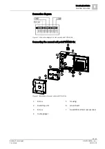
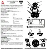
The manual call point is prepared for electrical connection. See the chapters
27]'.
1. Connect the feed line to the terminals in the switching unit (2), in accordance
with the connection diagram.
2. If using shielded cables:
– NOTICE! The shielding must not touch any external potentials.
– Connect the shielding for the detector line cable (LINE) to an auxiliary
terminal in the housing.
– Connect the shielding of the external alarm indicator cable with the positive
pole of the external alarm indicator connection.
3. NOTICE! Avoid crushing the cables! Observe the feed line when inserting the
switching unit (2) into the housing (5).
4. Insert the switching unit (2) into the housing (5) with the terminals facing
upwards.
5. Secure the switching unit (2) with two screws (1).
6. Close the housing (5) with the door.
a
The manual call point is now electrically connected.

