background image

Safety
Standards and directives complied with

2

16 | 42
Building Technologies

A6V10349616_i_en_--

Fire Safety

2019-01-18

Disclaimer

We have checked that the content of this document matches the hardware and

software described. Despite this, we cannot rule out deviations and cannot

therefore assume liability for them matching completely. The details in this

document are checked regularly and any corrections needed included in

subsequent editions.

We are grateful for any suggestions for improvement.

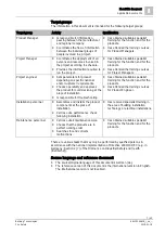
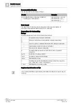
2.3 Standards and directives complied with

A list of the standards and directives complied with is available from your Siemens

contact.

2.4 Release Notes

Limitations to the configuration or use of devices in a fire detection installation with

a particular firmware version are possible.

WARNING

Limited or non-existent fire detection
Personal injury and damage to property in the event of a fire.

Read the 'Release Notes' before you plan and/or configure a fire detection

installation.

Read the 'Release Notes' before you carry out a firmware update to a fire

detection installation.

NOTICE

Incorrect planning and/or configuration
Important standards and specifications are not satisfied.
Fire detection installation is not accepted for commissioning.
Additional expense resulting from necessary new planning and/or configuration.

Read the 'Release Notes' before you plan and/or configure a fire detection

installation.

Read the 'Release Notes' before you carry out a firmware update to a fire

detection installation.
Summary of Contents for FDM223-Ex

Page 1: ...FDM223 Ex Manual call point Technical Manual A6V10349616_i_en_ Building Technologies 2019 01 18 Control Products and Systems ...

Page 2: ...nication thereof to others without express authorization are prohibited Offenders will be held liable for payment of damages All rights created by patent grant or registration of a utility model or design patent are reserved Issued by Siemens Switzerland Ltd Building Technologies Division International Headquarters Theilerstrasse 1a CH 6300 Zug Tel 41 58 724 2424 www siemens com buildingtechnologi...

Page 3: ...al 17 3 1 3 Product version ES 18 3 2 Setup 19 3 2 1 Manual call point FDM223 Ex 19 3 2 2 Connections 20 3 2 3 Indication elements 20 3 3 Function 21 3 3 1 Danger levels 21 3 3 2 Internal alarm indicator 21 3 3 3 Test mode 21 3 3 4 Diagnosis levels 21 3 3 5 Behavior in degraded mode 22 3 3 6 Line tester 22 3 4 Accessories 23 3 4 1 Glass insert DMZ1196 AC 23 3 4 2 Protective cover DMZ1197 AC 23 3 4...

Page 4: ... 2 Checking function 33 7 Maintenance troubleshooting 34 7 1 Resetting after an alarm 34 7 2 Status query 34 7 3 Performance check 34 7 4 Replacing the glass insert 35 8 Specifications 36 8 1 Technical data 36 8 2 Dimensions 38 8 3 Master gauge for recesses 38 8 4 Environmental compatibility and disposal 39 Glossary 40 Index 41 ...

Page 5: ...ocument is aimed at users who are planning installing commissioning operating and maintaining a fire detection installation FS20 FS720 or SIGMASYS with a line card FDnet C NET with addressed detector lines within the scope of the ATEX directive or IECEx General knowledge about the structure and function of fire detection installations FS20 FS720 is required in order to understand the information W...

Page 6: ...4 Ga Ta 35 70 C II 1 D Ex ia IIIB T135 C Da Ta 35 70 C When used in atmospheres at risk of gas explosion The manual call point FDM223 Ex must be protected against electrostatic charging along with all its accessory parts Intended use The manual call point FDM223 Ex may only be used as follows On an FDnet Ex C NET Ex detector line in a fire detection installation FS20 FS720 On the detector line the...

Page 7: ...perability and approves the product for commissioning at the place of installation Is responsible for troubleshooting Has obtained suitable specialist training for the function and for the products Has attended the training courses for Product Engineer Installation personnel Assembles and installs the product components at the place of installation Carries out a performance check following install...

Page 8: ... shown in this document as follows Requirement for a behavior instruction 1 2 Behavior instruction with at least two operation sequences Version option or detailed information for a behavior instruction Intermediate result of a behavior instruction End result of a behavior instruction Numbered lists and behavior instructions with an operation sequence X Reference to a page number Text Quotation re...

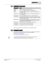
Page 9: ... FDAI93EX AI330 DCA1191 DJZ1193 A6V10324618 Planning Mounting Installation Commissioning Maintenance of fire detection installations with addressed detector lines in potentially explosive atmospheres A6V10333771 Technical Manual Line adapter Ex FDCL221 Ex A6V10349347 Data sheet Manual call point FDM223 Ex A6V10349619 Installation Manual call point FDM223 Ex Please also observe the documentation fo...

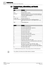
Page 10: ...ght emitting diode Symbol Meaning C 0 Maximum external capacity C C Maximum permissible cable capacitance C i Maximum internal capacity I 0 Maximum output current I i Maximum input current L 0 Maximum external inductivity L C Maximum permissible cable inductance L i Maximum internal inductivity P 0 Maximum output power P i Maximum input power R C Resistance of the connection cable T a Ambient temp...

Page 11: ...interior views of the manual call point door amended throughout the entire document Cable grippers 2 hole removed from accessories available to order Editorial changes h 2015 02 02 Table listing published language versions corrected IP protection category amended in Technical data chapter seal DMZ1197 AD added in Accessories chapter editorial changes g 2014 07 22 Editorial changes f 2014 05 23 Edi...

Page 12: ...protect people and property The safety notices in this document contain the following elements Symbol for danger Signal word Nature and origin of the danger Consequences if the danger occurs Measures or prohibitions for danger avoidance Symbol for danger This is the symbol for danger It warns of risks of injury Follow all measures identified by this symbol to avoid injury or death Additional dange...

Page 13: ...us situation which could result in slight to moderately serious injury if you do not avoid this situation NOTICE NOTICE identifies a possibly harmful situation or possible damage to property that may result from non observance NOTICE does not relate to possible bodily injury How risk of injury is presented Information about the risk of injury is shown as follows WARNING Nature and origin of the da...

Page 14: ...reas to prevent them being switched back on again by mistake Label the connection terminals with external external voltage using a DANGER External voltage sign Route mains connections to products separately and fuse them with their own clearly marked fuse Fit an easily accessible disconnecting device in accordance with IEC 60950 1 outside the installation Produce earthing as stated in local safety...

Page 15: ...sks Written confirmation must be obtained from Siemens and the corresponding safety bodies for modifications or additions No changes may be made to devices with EC type examination certificates Modules and spare parts Components and spare parts must comply with the technical specifications defined by Siemens Only use products specified or recommended by Siemens Only use fuses with the specified fu...

Page 16: ... Limitations to the configuration or use of devices in a fire detection installation with a particular firmware version are possible WARNING Limited or non existent fire detection Personal injury and damage to property in the event of a fire Read the Release Notes before you plan and or configure a fire detection installation Read the Release Notes before you carry out a firmware update to a fire ...

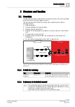
Page 17: ...the FDnet Ex C NET Ex downstream of a line adapter Ex FDCL221 Ex Can be addressed on the FDnet Ex C NET Ex detector line Figure 1 Use of a manual call point FDM223 Ex on the FDnet Ex downstream of a line adapter Ex FDCL221 Ex 3 1 1 Details for ordering Type Order number Designation FDM223 Ex complete S54329 F5 A1 Red housing with glass insert Allen key switching unit 3 cable grippers 2 hole and No...

Page 18: ...packaging label Details of the product version can be found directly on the packaging label in the barcode Figure 2 Example of a packaging label with details of the product version Product version on the product label and the type plate Details of the product version can be found after the device order number Figure 3 Example of a product label with details of the product version Depending on the ...

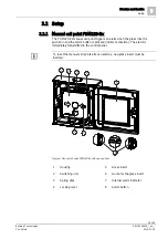
Page 19: ...s pushed in and the alarm button is pressed indirect activation The alarm is immediately transmitted to the control panel To reset the manual call points after an alarm a new glass insert must be inserted Figure 4 Manual call point FDM223 Ex with opened door 1 Housing 5 Glass insert 2 Switching unit 6 Guide for the glass insert 3 Spring clips 7 Internal alarm indicator 4 Locking lever 8 Alarm butt...

Page 20: ...ix spring clips on the top of the switching unit these are for the detector line and for connecting external alarm indicators Figure 5 Switching unit with spring clips 3 2 3 Indication elements A two color LED is built into the switching unit as an internal alarm indicator Figure 6 Switching unit with alarm indicator See also 2 Internal alarm indicator 21 ...

Page 21: ... per second Test mode is active Red Flashes once per second Localization is active o r Alarm is triggered Red and green alternating Flashes twice per second Alarm is triggered localization is active a n d Test mode is active See also 2 Indication elements 20 3 3 3 Test mode A test mode must be set on the control panel to test the manual call points When in test mode alarms from the manual call poi...

Page 22: ...ded mode operation on the FDnet C NET is not supported in the same way by all control panels The information in the List of compatibility and in the corresponding control panel documentation must be taken into account during project planning 3 3 6 Line tester WARNING Using the line tester FDUL221 during commissioning Risk of explosion Only operate the line tester FDUL221 in the area that is not at...

Page 23: ... BPZ 4942050001 3 4 2 Protective cover DMZ1197 AC For protection against unintended alarm activation Order number BPZ 5223550001 3 4 3 M20 x 1 5 metal cable gland For introducing a cable into the following devices Base attachment humid FDB293 Base attachment wet FDB295 Manual call point FDM223 Ex For cable diameters of 3 5 5 5 mm Temperature range 40 100 C Allows for increased IP protection Order ...

Page 24: ...tegory of the manual call point Order number BPZ 5470680001 3 4 5 Line adapter Ex FDCL221 Ex For operating peripheral devices on the FDnet Ex C NET Ex in areas at risk of explosion Electrical isolation of detector lines in an area at risk of explosion from detector lines in an area not at risk of explosion Mounting on a U rail TS35 or in a separate housing You will find more information in documen...

Page 25: ...he manual call point with various control panels Detector line Control panel FC20xx FC72x SIGMASYS AlgoRex FDnet Ex X X1 X 1 C NET Ex X X compatible X1 compatible with line card FDnet C NET not compatible You will find detailed information in the List of compatibility See also 2 Applicable documents 9 4 2 Fields of application The manual call points are intended for use in places where a fire can ...

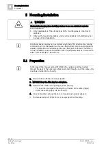
Page 26: ...or explosion protection are not damaged in a way that goes unnoticed Therefore it is only permitted to operate FDnet Ex C NET Ex peripheral devices in conjunction with a line adapter Ex FDCL221 Ex 5 1 Preparation In the case of the manual call point FDM223 Ex cables cannot be inserted through the back of the housing Cables must enter through one of the cable entry openings provided in the housing ...

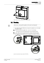
Page 27: ...ing height w The manual call point FDM223 Ex is prepared for installation See the chapter Preparation 26 1 Secure the housing at a height of 0 9 1 6 m on an even surface Only use the screw holes marked with arrows see diagram below 2 Pull the cables into the housing through the openings in the cable gripper a The manual call point FDM223 Ex is now prepared for electrical connection Figure 8 Screw ...

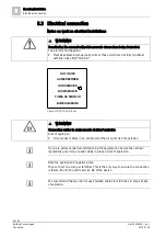
Page 28: ...ecting cables in environments at risk of explosion Risk of explosion Only connect cables in an environment that is not at risk of explosion If you are permanently decommissioning the equipment observe the national regulations governing unused cables in areas at risk of explosion Note the positive and negative poles Only connect one wire per terminal This is the only way to ensure the connection is...

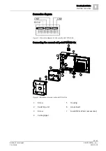
Page 29: ... Connection diagram Figure 10 Connection diagram for manual call point FDM223 Ex Connecting the manual call point FDM223 Ex Figure 11 Installation of manual call point FDM223 Ex 1 Screw 5 Housing 2 Switching unit 6 Glass insert 3 Screw 7 Seal DMZ1197 AD accessories 4 Cable gripper LINE LINE Ext AI 2 3 4 5 4 6 4 1 7 ...

Page 30: ... the chapters Preparation 26 and Mounting 27 1 Connect the feed line to the terminals in the switching unit 2 in accordance with the connection diagram 2 If using shielded cables NOTICE The shielding must not touch any external potentials Connect the shielding for the detector line cable LINE to an auxiliary terminal in the housing Connect the shielding of the external alarm indicator cable with t...

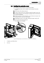
Page 31: ...insert See the chapter Replacing the glass insert 35 3 Thread the protective cover 1 through the opening in the door from the front as shown in the diagram 4 Insert the pivot pins 2 for the protective cover 1 in the two recesses on the rear side of the door as shown in the diagram 5 Install the glass insert See the chapter Replacing the glass insert 35 6 Close the door of the manual call point a T...

Page 32: ... device testing The manual call points have an internal alarm indicator This alarm indicator may as well be activated from the control panel for localization and device testing The LED indicator of the alarm indicator has the following meanings LED indication Meaning Off Normal condition Green Flashes once per second Test mode is active Red Flashes once per second Localization is active o r Alarm ...

Page 33: ...key 3 Press the alarm button a The alarm signal is transmitted 4 Check whether an alarm is displayed on the fire control panel 5 Push the black locking lever 1 in the upper right corner to the right until it clicks a The alarm button is now protruding by approx 5 mm 6 Close the door of the manual call point a The manual call point is ready for operation again 7 Set the detector line to Normal oper...

Page 34: ...ht corner of the switching unit to the right until it clicks a The alarm button is now protruding by approx 5 mm 6 Close the door of the manual call point 7 Carry out a performance check See the chapter Checking function 33 a The manual call point is ready for operation again 7 2 Status query Status query on the control panel Depending on the authorization level of the user and the control panel t...

Page 35: ...ss insert proceed as follows w The door of the manual call point is open See the chapter Preparation 26 1 Remove all the remains of the old glass insert 2 Insert the new glass insert between the guides 1 and slide it down as far as the stop behind the retainer 2 You may need to manipulate the glass insert slightly before it will slide into the retainer 2 a The glass is fitted in the door 3 Check t...

Page 36: ... L 0 100 µH C 0 38 nF Only for connecting passive external alarm indicators with negligibly low inductance and capacitance levels You will find an explanation of the formula symbols in chapter Technical terms abbreviations and formula symbols 10 You will find information on approvals CE marking and the relevant EU directives for this device these devices in the following document s see Applicable ...

Page 37: ...g clips Conductor cross section 1 1 5 mm Ambient conditions Operating temperature 25 70 C Storage temperature 35 75 C Air humidity 95 rel Protection categories IEC 60529 Manual call point IP44 Manual call point with seal DMZ1197 AD accessories IP66 Environmental category according to EN 54 11 In buildings and outdoor areas Electromagnetic compatibility 1 MHz 1 GHz 50 V m 1 GHz 2 GHz 30 V m Mechani...

Page 38: ...ns Dimensions 8 38 42 Building Technologies A6V10349616_i_en_ Fire Safety 2019 01 18 8 2 Dimensions 8 3 Master gauge for recesses 134 3 134 3 42 5 A A A Ø 4 8 A A 122 65 120 15 116 65 123 65 10 65 14 15 11 65 18 15 ...

Page 39: ...easures have been undertaken Use of reusable materials Use of halogen free plastics Electronic parts and synthetic materials can be separated Larger plastic parts are labeled according to ISO 11469 and ISO 1043 The plastics can be separated and recycled on this basis The device is considered an electronic device for disposal in accordance with the European Guidelines and may not be disposed of as ...

Page 40: ...t on any of the energy limited circuits Qualified person A qualified person is someone who as a result of their professional training and current occupational activities has the knowledge required to test the work equipment In some cases the relevant national ordinances such as the Ordinance on Industrial Safety and Health in Germany make distinctions according to different qualification requireme...

Page 41: ...ink 5 URL 9 E Environmental compatibility 39 ES Product version 18 EU directives 36 F Fire control panel failure Degraded mode operation 22 I Installation in wet areas 27 Intended use 6 Internal alarm indicator 21 32 Internet 5 L List of compatibility 22 25 M Maintenance intervals 34 Manual call point Test mode 21 Manufacturer 6 O Operating temperature 37 Original language 7 P Packaging label Prod...

Page 42: ...on International Headquarters Theilerstrasse 1a CH 6300 Zug 41 58 724 2424 www siemens com buildingtechnologies Siemens Switzerland Ltd 2012 Technical specifications and availability subject to change without notice Document ID A6V10349616_i_en_ Edition 2019 01 18 ...

Reviews: