Siemens FCM2041-U3 Installation Instructions Manual Download Page 3

Siemens Industry, Inc.
Building Technologies  Division

A6V11231630_en--_b

3

INSTALLATION

Remove ELECTRICAL POWER prior to installing the FCM2041-U3 in the enclosure.

Set the Network Address

Remove the FCM2041-U3 from its anti-static bag. Set the two-digit address using
the 10-position rotary switches (S2, S3) located on the back of the FCM2041-U3. For
a standalone HNET panel, set the address of the FCM2041-U3 to 01. Be sure to set
leading zeros. In the Zeus Physical View, make sure that the FCM2041-U3 is config-
ured at address 253.

When the FCM2041-U3 is used for networking with other panels, set the two-digit
network address to the XNET node address that has been assigned in Zeus. Be sure to
set leading zeros. For example, Node 2 is set at 02. In the Zeus Physical View, the
HNET address of the PMI is automatically set to 253 when operating in an XNET panel.

The table below details the differences between the network address settings in a
FCM2041-U3 and a PMI.

S

E

H

C

T

I

W

S

S

S

E

R

D

D

A

K

R

O

W

T

E

N

E

H

T

G

N

I

T

T

E

S

3

U

-

1

4

0

2

M

C

F

y

r

a

t

o

R

f

o

r

e

b

m

u

N

s

e

h

c

t

i

w

S

s

s

e

r

d

d

A

o

w

T

)

3

S

,

2

S

(

)

e

n

o

l

a

d

n

a

t

S

(

T

E

N

H

)

I

M

P

n

o

g

n

i

t

t

e

S

(

.

1

0

o

t

s

s

e

r

d

d

a

t

e

S

.

)

h

c

t

i

w

s

s

n

o

i

t

p

O

(

4

S

n

o

g

n

i

t

t

e

s

o

N

)

s

u

e

Z

n

i

g

n

i

t

t

e

S

(

t

a

d

e

r

u

g

i

f

n

o

c

s

i

3

U

-

1

4

0

2

M

C

F

e

h

t

e

r

u

s

e

k

a

M

.

w

e

i

v

l

a

c

i

s

y

h

p

s

u

e

Z

e

h

t

n

i

3

5

2

s

s

e

r

d

d

a

)

k

r

o

w

t

e

N

(

T

E

N

X

)

I

M

P

n

o

g

n

i

t

t

e

S

(

.

)

h

c

t

i

w

s

s

n

o

i

t

p

O

(

4

S

n

o

g

n

i

t

t

e

s

o

N

t

i

g

i

d

-

o

w

t

e

h

t

o

t

s

s

e

r

d

d

a

e

d

o

n

T

E

N

X

e

h

t

t

e

S

.

s

u

e

Z

n

i

t

i

r

o

f

d

e

n

g

i

s

s

a

s

s

e

r

d

d

a

)

s

u

e

Z

n

i

g

n

i

t

t

e

S

(

m

o

r

f

(

s

s

e

r

d

d

a

e

d

o

n

t

i

g

i

d

-

o

w

t

T

E

N

X

e

h

t

t

e

S

o

t

e

r

u

s

e

B

.

e

e

r

t

l

a

c

i

s

y

h

p

s

u

e

Z

e

h

t

n

i

)

4

6

-

1

0

.

s

o

r

e

z

g

n

i

d

a

e

l

t

e

s

Mount the FCM2041-U3

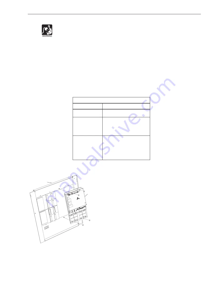
The FCM2041-U3 mounts to the rear of the inner door in the CAB-1, CAB-2, CAB-3,

REMBOX2 or REMBOX4 enclosures. Select the location of the
FCM2041-U3. It can be mounted either in the center or on the left
side of the inner door, when viewed from the outside of the
enclosure. Place the FCM2041-U3 onto the inner door from the rear,
over the four mounting studs in the desired location. Secure the
FCM2041-U3 to the inner door with the four nuts provided. (Refer to
Figure 4.)

A 40 inch long 60 wire cable, P/N 555-133743, connects the
FCM2041-U3 to the CC-5.  The CC-5 is located in the back of the
enclosure on the left hand side. Connect one end of the cable to J2
on the FCM2041-U3. J2 is marked with “CC-5” on the FCM2041-U3
printed circuit board. Connect the other end of the cable to P1 on the
CC-5. (Refer to Figure 5.)

Connect the FCM2041-U3 to the RNI in  a REMBOX2/4.  The RNI is
located in the back of the enclosure on the top left hand side.
Connect one end of the cable to J2 on the FCM2041-U3. J2 is

                          marked with “CC-5” on the printed circuit board. Connect the other
                           end of the cable to JP1 on the RNI. (Refer to Figure 6.)

Figure 4

Mounting the FCM2041-U3 to

the Rear of the Inner Door

INNER DOOR

FCM2041-U3

Summary of Contents for FCM2041-U3

Page 1: ...2041 U3 contains a full VGA LCD Touch Screen and LEDs for displaying system status An audible sounds when there are unac knowledged events on the FCM2041 U3 The display is surrounded by keys that are used to control the displayed information and to navigate through these screens Keys are also provided to obtain help and to enter into the menu features of the FCM2041 U3 Refer to Figure 1 On the bac...

Page 2: ... s e r d r a h r o f s d n o c e s 5 d l o H 2 1 D S I M P G e r o t s o t d e s u t r o p d r a c D S n o i t a m r o f n i p u k c a b d n a e s a b a t a d 2 D S I M P G w o l l a o t d e s u t r o p d r a c D S y t i l i b a p a c S U T A T S l a m r o n e t a c i d n i o t t h g i l s t n e m g e s g n i k l a W n a f i d e y a l p s i d s i e d o c r o r r E n o i t a r e p o d e t c e t e d...

Page 3: ... t e N T E N X I M P n o g n i t t e S h c t i w s s n o i t p O 4 S n o g n i t t e s o N t i g i d o w t e h t o t s s e r d d a e d o n T E N X e h t t e S s u e Z n i t i r o f d e n g i s s a s s e r d d a s u e Z n i g n i t t e S m o r f s s e r d d a e d o n t i g i d o w t T E N X e h t t e S o t e r u s e B e e r t l a c i s y h p s u e Z e h t n i 4 6 1 0 s o r e z g n i d a e l t e s M...

Page 4: ...vents are acknowledged a reset button becomes available in the lower right side of the display If notification appliances were active two additional buttons appear at the bottom of the screen These allow the operator to silence or unsilence the notification appliances When the notification appliances are silenced the Audibles Silenced LED lights The system can only be reset with the notification a...

Page 5: ...s tool replace the PMI with the new FCM2041 U3 Please make sure you are converting the correct PMI with a FCM2041 U3 by match ing the address of the switches on the back of the PMI a In the configuration which you have just removed from the original PMI click on the PMI module in the physical tree Select the Edit menu and click on Find ReplaceTree Node A dialog box will open and allow you to repla...

Page 6: ...sfer theTransfer Progress dialog displays transfer progress and status messages and allows you to cancel the transfer When you click OK at the transfer complete message the control panel will reset itself with the new configuration ELECTRICAL RATINGS r e w o P t u p n I r e w o P t u p t u O t n e r r u C e n a l P k c a B V 4 2 A m 5 9 1 d n a T E N X T E N H h c a E r i a P k r o w t e N N A C x...

Page 7: ...needs Such a security concept may result in additional site specific preventive action to ensure that the building comfort fire safety security management or physical security system for your site are operated in a secure manner These measures may include but are not limited to separating networks physically protecting system components user awareness programs defense in depth etc For additional i...

Page 8: ...nc Building Technologies Division Florham Park NJ Siemens Canada Ltd 1577 North Service Road East Oakville Ontario L6H 0H6 Canada Document ID A6V11231630_en _b This page has been left intentionally blank P N A5Q00075185 ...

Reviews: