5
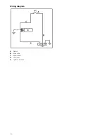
than 1.2 m long and installed in accordance with AS/NZS
5601.1.
Ensure that the hose does not contact the hot surfaces of the
hotplate, oven, dishwasher or any other appliance that may
be installed underneath or next to the hotplate. The hose
should not be subjected to abrasion, kinking or permanent
deformation and should be able to be inspected along its
entire length with the cooktop in the installed position. Unions
compatible with the hose fittings must be used and all
connections tested for gas leaks.
The supply connection point shall be accessible with the
appliance installed.
WARNING: Ensure that the hose assembly is restrained from
accidental contact with the flue outlet of an underbench oven.
Before Leaving- Check all connections for gas leaks with soap
and water. DO NOT use a naked flame for detecting leaks.
Ignite all burners both individually and concurrently to ensure
correct operation of gas valves, burners and ignition. Turn gas
taps to low flame position and observe stability of the flame for
each burner individually and all together. Adhere the duplicate
data plate to an accessible location near the hotplate. When
satisfied with the hotplate, please instruct the user on the
correct method of operation. In case the appliance fails to
operate correctly after all checks have been carried out, refer to
the authorised service provider in your area.
It should be expressly noted that we cannot accept any liability
for direct or indirect damage caused by wrong connection,
leakage or improper installation. When being repaired, the
appliance must always be disconnected from the mains supply;
if required, notify our customer service.
Converting the cooktop from Nat. Gas to
Universal LPG
To change injectors
All work involved in installation, setting and adaptation to a
different gas type must be carried out by authorised personnel
from our Service Centre and must comply with current
regulations and the conditions laid down by the local gas
company.
Request change-over injectors from our customer service
deparment (refer injector chart below for sizes).
Before conversion the cooktop must be disconnected from the
electricity and gas valves must be turned to the OFF position.
Changing the nozzles of the burners on the
cooktop
1.
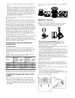
Remove the pan supports, burner covers and diffusers.
2.
Change the nozzles using the spanner provided by our
Service Centre (code 340847, for double and triple flame
burners code 340808), taking special care to ensure that the
nozzle does not fall when it is removed from the burner or
when fitted.
Ensure that it is completely tightened in order to guarantee
the seal.
Adjustment of the taps
1.
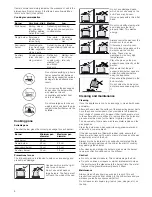
Set the control knobs to minimum.
2.
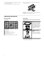
Remove the control knobs from the taps. It has a flexible
rubber valve reinforcing ring. Press with the tip of the
screwdriver to access the tap's adjusting screw.
Never remove the valve reinforcing ring.
The valve
reinforcing rings guarantee the watertightness of the
appliance's interior from liquids and dirt, which might
otherwise prevent its correct operation.
3.
Adjust the minimum ring setting by turning the by-pass screw
using a flat head screwdriver.
To adjust the minimum flame for N.G. replace the control
knob onto the spindle, light the gas and turn the control knob
to the small flame position. Screw the adjustment screw anti-
clockwise to estabilish a minimum stable flame position. The
flame should remain alight and not burn back to the injector
when the valve is turned quickly from ‘Full On’ to the
“Minimum flame” position and back a few times. To adjust
the minimum flame position for ULPG the screw must be fully
tightened down clockwise.
4.
Refit the control knobs.
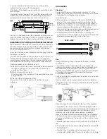
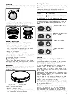
If the by-pass screw cannot be accessed, disassemble the
grease drip tray, which is fixed to the rest of the hob using a
clip and screw mounting system. The following steps must be
taken to remove it:
1.
Remove all pan supports, burner caps, diffusers and control
knobs.
2.
Loosen the screws on the burners.
Use the disassembly lever 483196 available from our
Technical Assistance Service. To release the front clips, apply
the lever to the area shown in figure below.
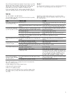
Natural Gas
Universal LPG
Burner
Hourly Gas
Consumption
(MJ)
Injector
mark
Hourly Gas
Consumption
(MJ)
Injector
mark
Auxiliary
3,60
90
3,50
50
Semi-rapid
6,50
118
6,00
67
Rapid
10,80
155
10,00
85
Wok
18
85/140 18
46/71

