Siemens DOME COLOUR CFMC1315-LP, Configuration
The Siemens DOME COLOUR CFMC1315-LP is a top-of-the-line surveillance camera that ensures your safety and security. For your convenience, we provide free downloadable Installation Instructions manual on our website, allowing you to easily set up and operate this cutting-edge product with ease. Visit manualshive.com and enhance your security today.
Share
Download


Reviews:
No comments
Related manuals for DOME COLOUR CFMC1315-LP
DSC-350 - Digital Camera - 0.35 Megapixel
Brand: D-Link Pages: 2

DCS-932L
Brand: D-Link Pages: 2

DSH-C310
Brand: D-Link Pages: 2

DCS-932L
Brand: D-Link Pages: 40

DCS-5020L
Brand: D-Link Pages: 5
DCS-5020L
Brand: D-Link Pages: 67

DCS-2136L
Brand: D-Link Pages: 8

DSC-100
Brand: D-Link Pages: 8

DCS-2530L
Brand: D-Link Pages: 6

DCS-820L
Brand: D-Link Pages: 4

DCS-60
Brand: D-Link Pages: 2
DSC-350 - Digital Camera - 0.35 Megapixel
Brand: D-Link Pages: 2

DCS-8330LH
Brand: D-Link Pages: 41

DWC-BL2651TIR
Brand: DW Pages: 32

BPI-D1
Brand: Banana Pi Pages: 12
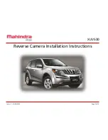
XUV500
Brand: Mahindra Pages: 12

UM-200
Brand: Uniq Pages: 13

ZN-B2MTP
Brand: Ganz Pages: 50


