background image

7 / 14

Siemens

RXC39.5 – Room controller

CM2N3856en_06

Building Technologies

2013-12-14

Commissioning

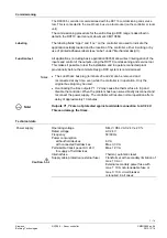
The RXC39.5 controller is commissioned with the RXT10 commissioning and service
tool. This is connected to the L

ON

W

ORKS

 bus via a tool socket (on the controller or room

unit).

The commissioning procedure for the entire Desigo RXC range is described in
detail in the RXT10 user manual, document CM110669.

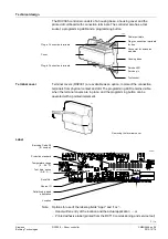
The labeling fields “Appl.” and “Loc.” on the controller are used to indicate the
application actually loaded and the location of the controller, either in writing or by
use of printed adhesive labels (see “Label” under “Mechanical design”).

All applications (including basic application 00039) allow direct interrogation of the
inputs and control of the outputs using the RXT10 commissioning and service tool.
This makes it possible to test the installation and to operate connected plant
provisionally before the complete Desigo RXC system is commissioned.

·

  The L

ON

W

ORKS

 bus plug (terminals 23 and 24) can be removed and

reconnected at any time, even while the controller is in operation. Only the
original bus plug may be used.

·

  Overloading the triac outputs Y1, Y2 may cause the thermal fuse to trip and

disable the controller. When the problem has been solved briefly disconnect and
reconnect the power supply. The controller will resume normal operation after a
delay of approximately 10 minutes.

Outputs Y1, Y2 are not protected against accidental connection to AC 24 V.
This can damage the triacs.

Technical data

Power supply

Operating voltage

SELV / PELV AC 24 V ± 20 %

Rated voltage

AC 24 V

Frequency

50/60 Hz

Power consumption

without field devices
with connected field devices

6 VA
Max. 33 VA

Permissible transit power AC 24 V

for supply of field devices

Max. 12 VA

Internal fuse

Thermal, automatic reset

Caution

Supply cable protection (external fuse)

Transformer with secondary limitation of
max. 10 A or
External secondary power fuse with
max. T 10 A non-renewable fuse or
max. C 13 A circuit breaker
is required in all cases

Labeling

Function test

Notes

STOP

Note!

Summary of Contents for Desigo RXC39.5

Page 1: ... systems with ECM fan PI PID control depending on application Downloadable application software LONMARK compatible bus communications For use in the Desigo building automation and control system 0 10 V control of valve actuators fan and electric heating coil Volt free relay contacts for release of the fan and the electric heating coil Commissioning with RXT10 or standard LONWORKS tool AC 24 V oper...

Page 2: ...ning In conjunction with a building automation and control system the RXC39 5 controller can also be used as a universal I O module e g to register digital signals or to control various equipment ON OFF or modulating In this case the controller is loaded with basic application 00039 The inputs can then be read and the outputs overridden via the building automation and control system Functions The ...

Page 3: ...socket Terminal covers RXZ30 1 are available as an option to protect the connection terminals from physical contact and dirt The programming LED remains visible when the terminal covers are in place and the programming button can be operated with a pointed implement 80049 Removing the terminal cover Bar code Code 39 ID number Protection standard Temperature range 0 50 C Test date series A B C Seri...

Page 4: ...munication with the PXR system controller or the NIDES RX interface to Desigo other Desigo RXC devices LONMARK compatible third party devices e g presence detector PPS2 terminals CP and CP Interface to the QAX room units In addition to PPS2 the LONWORKS bus is also looped to the tool socket on the room unit Tool socket RJ45 on the controller or room unit for RXT10 commissioning and service tool LO...

Page 5: ... supply cable must be protected with at least 10 A The controlled devices valve damper actuators are supplied directly from the controller The maximum load on the outputs must not be exceeded see Technical data This device has no circuit breakers for supply lines to external consumers field power supply Line insulation must always be sufficient for the available rated voltage When forwarding suppl...

Page 6: ... 24 V supply outputs for field devices G terminals 5 27 29 33 37 may be charged with a total of max 12 VA Mounting The room controllers can be mounted in any orientation and fixed as follows 80060 80061 Rail mounting The housing base is designed for snap mounting on DIN rails type EN50022 35x7 5 can be released with a screw driver Surface mounting There are four drill holes for screw mounting see ...

Page 7: ...system is commissioned The LONWORKS bus plug terminals 23 and 24 can be removed and reconnected at any time even while the controller is in operation Only the original bus plug may be used Overloading the triac outputs Y1 Y2 may cause the thermal fuse to trip and disable the controller When the problem has been solved briefly disconnect and reconnect the power supply The controller will resume nor...

Page 8: ... K at 25 C Outputs SELV Field supply G G0 Caution Output voltage Fuse AC 24 V transit power No internal fusing Fusing on the supply line required under all circumstances Triac Y1 Y2 Output voltage AC 24 V Permissible load current Max 0 5 A Power limitation Fuse T 2 A can not be changed common for both triacs Total nominal load load on both outputs simultaneously Max 12 VA DC 0 10 V Resolution 3 mV...

Page 9: ...on standard to EN 60529 IP30 with terminal cover fitted and wall mounted without DIN rail IP20 for all other mounting arrangements Protection class Insulation protection class III Ambient conditions Normal operation Class 3K5 to IEC 60721 3 3 Temperature 0 50 C Humidity 85 r h Transport Class 2K3 to IEC 60721 3 2 Temperature 25 65 C Humidity 95 r h Standards and directives Product standards EN 607...

Page 10: ...d Signal inputs for volt free contacts D1 10 Signal input GND 11 Signal ground D2 12 Signal input D3 13 Signal input GND 14 Signal ground D4 15 Signal input Room unit CP 16 PPS2 ground CP 17 PPS2 data CLA 18 LONWORKS Data A CLB 19 LONWORKS Data B LONWORKS Bus CLA 20 LONWORKS Data A CLB 21 LONWORKS Data B Relay outputs Q11 22 Feed for Q12 Q12 23 Normally open contact max AC 250 V 1 8 KW Q21 24 Feed...

Page 11: ...0 V loads Y01 Y02 Thermal actuators Y1 Y4 Motorized AC 24 V actuators Twisted pair STOP Note For Q1 Q2 use external fuses of max 10 A to protect the PCB tracks Notes Do not exceed the maximum simultaneous load on outputs Y1 Y2 see Engineering A power amplifier may be used to connect additional valve actuators to Y1 and Y2 see Desigo RXC installation guide CA110334 For information on actuators comp...

Page 12: ...d Differing voltage of the power supply of the controller and the supply of the power amplifier may cause big differences in the position of the valves N1 RXC39 5 N2 UA1T see data sheet CA2N3591 Y5 AC 24 V thermal valve actuator Y5 1 AC 24 V thermal valve actuator 1 2 3 4 COM 8 7 6 5 COM COM 1 2 3 4 COM 8 7 6 5 COM COM N1 RXC39 5 N2 UA1T see data sheet CA2N3591 Y5 AC 24 V thermal valve actuator Y5...

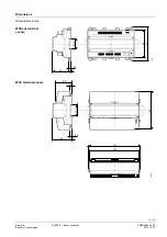
Page 13: ...s RXC39 5 Room controller CM2N3856en_06 Building Technologies 2013 12 14 Dimensions Dimensions in mm 62 35 3 90 3876M01 1 3 9 110 62 1 3 9 35 3 3876M02 120 152 50 6 161 Without terminal covers With terminal covers ...

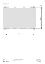
Page 14: ...14 14 Siemens RXC39 5 Room controller CM2N3856en_06 Building Technologies 2013 12 14 100 135 80056 Drilling diagram ã 2012 2013 Siemens Switzerland Ltd Subject to change ...

Reviews: