background image


9/14 

Siemens 

RXC32 – Room controller for VAV systems 

CA2N3845en_06 

Building Technologies 


2013-06-18 

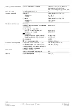
Outputs 

Caution


Supply outputs For field supply 

Output voltage 
Fuse 

 
AC 24 V (transit power)  

No internal fusing 

Fusing on the supply line required 
under all circumstances 


Triac outputs AC 24 V 

Quantity  
Output voltage 
 
Permissible load current 
Power limitation 
 
Total nominal load  
(load on all triacs simultaneously) 

 
4 (Y1 ... Y4) 
AC 24 V on/off, PDM or 3-position 
(selected by switch) 
Max. 0.5 A 

1.85A PTC, resetting  

(common for all triacs) 
Max. 24 VA 

Flow sensor


Tube connections (nipple diameters) 
Measuring range 
Overload range 
Volume measurement 

Accuracy with dynamic calibration 
Accuracy with static calibration 

 5.2 mm 

0…300 Pa 
0…100 k Pa 
 
CEN TC247 Accuracy class 2 
CEN TC247 Accuracy class 1 


Air filter 

Example: air filter ALG 3 ½ SPF Can be ordered from Schupp AG 
 

Interfaces 

Interface with room unit 

Number of room units connectable  
Interface type  

for room unit 


for RXT10 

PPS2 baud rate 
LON baud rate 

 
Max. 1 
PPS2 
LON 
4.8 kBit/s 
78 kBit/s 


L

ON

W

ORKS

®-Bus 

Interface type 
 
Transceiver 
 
Baud rate 
Bus topology and bus termination 

 
LON (L

ON

M

ARK

-compatible),  

electrically isolated 
on RXC32.1: FTT-10A 
on RXC32.5: FT 5000 
78 Kbps 
See Installation guide, CA110334 

Cable connections 

Plug-in terminal blocks


Solid conductors


Stranded conductors without 
connector


sleeves


Stranded conductors with connector sleeves 
(DIN 46228/1) 


Rising cage terminals 

1 x 0.2 

... 2.5mm

2


or 2 x 0.2 ... 1.0 mm


1 x 0.2 

... 2.5mm

2


or 2 x 0.2 ... 1.5 mm


1 x 0.25 

... 2.5mm

2


or 2 x 0.25 ... 1.0 mm


Max. tightening torque


0.6 Nm


Single cable lengths 

Signal inputs D1, D2 
Measured value input X1 
Triac outputs AC 24 V, Y 1 … Y4 
Interface to room unit 
 
  Cable type 
L

ON

W

ORKS

® bus 

  Cable type 
Tool connecting cable 

See Installation guide, CA110334 
Max. 100 m with diameters 

 0.6 mm 

Max. 100 m with diameters 

 0.6 mm 

Max. 100m where A 

 1.5 mm

2


Max. 115 m where A= 0.75 mm

2


(including tool connecting cable) 
4-core, twisted pair, unscreened 
See Installation guide, CA110334 
Max. 3 m length 


Summary of Contents for Desigo RXC32.1

Page 1: ...dual rooms Control of the supply or extract air with volume control dampers with or without reheaters Downloadable application software LONMARK compatible bus communications For use in the Desigo building automation and control system Control of damper actuators with AC 24 V 3 position signal Control of electric or LPHW reheaters with AC 24 V or AC 24 V 3 position signals Built in air flow sensor ...

Page 2: ...ontrol with AC 24 V In this case the controller is loaded with basic application 00032 The inputs can then be read and the outputs overridden via the building automation and control system Functions The controller functions are determined by the selected application and its parameters For a detailed description of functions refer to the Desigo RXC applications library V1 CA2A3810 V2 CA110300 Certa...

Page 3: ...tibility For operation of the RXC32 room controller a room unit from the QAX series may be used in conjunction with conventional momentary contact switches for lighting and blind control Alternatively the flexible room units QAX50 1 or QAX51 1 may be used See the RX hardware overview CA2N3804 for a summary of the available field devices Mechanical design The RXC32 controller consists of a housing ...

Page 4: ...e Code 128 Identification Identification number Protection standard Temperature range 0 50 C Test date series Z A B C Serial No Factory loaded application Definitive application Location Options for use of the labeling fields Appl and Loc Hand written entry of the location and the actual application or Printed adhesive label printed from the RXT10 commissioning and service tool All connection term...

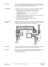
Page 5: ...its In addition to PPS2 the LONWORKS bus is also looped to the tool socket on the room unit Tool socket RJ45 on the controller or room unit for RXT10 commissioning and service tool LONWORKS bus RXT20 1 service terminal PPS2 The diagram below shows the wiring of the LONWORKS bus and PPS2 interface when a QAX room unit is connected It also shows the options for connecting the RXT10 commissioning and...

Page 6: ...vice has no circuit breakers for supply lines to external consumers field power supply Line insulation must always be sufficient for the available rated voltage When forwarding supply voltage for 24 V low voltage as well to external consumers the wiring cross sections must at any rate be adapted to the preswitched overcurrent protection device Please comply under all circumstances with local regul...

Page 7: ...he tubing Connect the connection to the higher pressure side and the connection to the lower pressure side The recommended tube length is in the range 700 mm 2 000 mm When using an air filter install it on the high pressure side with the air flowing through the filter in the correct direction Use an air filter to prevent the accumulation of dirt particle deposits on the sensor element especially w...

Page 8: ...l connection to AC 24 V This can damage the triacs For accurate measurement of the air volume make sure that the tubes are connected correctly Technical data Power supply Operating voltage SELV PELV AC 24 V 20 Rated voltage AC 24 V Frequency 50 60 Hz Power consumption Without field devices With field devices 6 VA Max 33 VA Caution Internal fuse Thermal automatic reset Supply cable protection exter...

Page 9: ...umber of room units connectable Interface type for room unit for RXT10 PPS2 baud rate LON baud rate Max 1 PPS2 LON 4 8 kBit s 78 kBit s LONWORKS Bus Interface type Transceiver Baud rate Bus topology and bus termination LON LONMARK compatible electrically isolated on RXC32 1 FTT 10A on RXC32 5 FT 5000 78 Kbps See Installation guide CA110334 Cable connections Plug in terminal blocks Solid conductors...

Page 10: ...d directives Product safety Automatic electronic controls for household and similar use EN 60730 1 Electromagnetic compatibility Immunity ndustrial residential EN 60730 1 Emissions residential EN 60730 1 compliance Meets requirements of EMC directive 2004 108 EC Meets requirements of RoHS directive 2011 65 EU UL compliance UL916 C Tick conformity EMC AS NZS 61000 6 3 Environmental compatibility Th...

Page 11: ...Ni1000 or DC 0 10 V M 13 Sensor ground Signal input for volt free contacts D1 14 Signal input GND 15 Signal input ground D2 16 Signal input GND 17 Signal input ground N C 18 Not connected Room unit CP 19 PPS2 ground CP 20 PPS2 data CLA 21 Data A CLB 22 Data B LONWORKS BUS plug in CLB 23 Data B CLA 24 Data A Triac outputs Y1 34 AC 24 V 0 5 A switching output G 35 AC 24 V actuator supply Y2 36 AC 24...

Page 12: ...ors Y3 1 Y4 1 AC 24 V contactors for electric heating coil Y3 3 Solid state relays AC24V Do not exceed the maximum simultaneous load on outputs Y1 Y4 see Engineering A power amplifier may be used to connect additional valve actuators to Y3 and Y4 see Desigo RXC installation guide CA110334 For information on actuators compatible with the RXC32 controller refer to the relevant application descriptio...

Page 13: ...ower supply of the controller and the supply of the power amplifier may cause big differences in the position of the valves AC 24 V 00105 H Y3 N1 Y1 G G G0 Y3 1 G G0 1 2 3 4 NS LS COM X1 AC 24 V Y3 1 Y3 2 00105 K Y3 8 7 6 5 COM Y1 COM Y1 N2 1 2 3 4 NS LS COM X1 Y3 5 Y3 6 8 7 6 5 COM Y1 COM Y1 N2 G G0 Y3 3 Y3 4 Y3 7 Y3 8 N1 Y1 G G G0 AC 24 V G G0 N1 RXC32 N2 UA1T see data sheet CA2N3591 Y3 AC 24 V ...

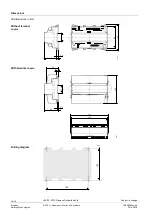
Page 14: ..._06 Building Technologies 2013 06 18 Dimensions 62 1 3 9 35 3 3845M02 110 90 62 1 3 9 35 3 3845M01 120 152 50 5 161 100 135 80056 All dimensions in mm Without terminal covers With terminal covers Drilling diagram 2000 2013 Siemens Switzerland Ltd Subject to change ...

Reviews: