Scanner Installation
CLSC3000
Hardware Installation
Installation Manual, CLSC004enI3c
10-4
©
Siemens AG 2010 / Date of issue: 2010-05-19
)
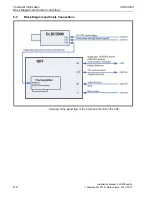
Feed the other end of the camera link cable through the machine to the
location of the IDH.
Refer to the respective machine documentation or drawing for the exact
path of laying the camera link cable.
Secure the cable position with cable ties.
Note!
Excess cable length may be laid in loops.
Minimum bending radius of the camera link cable is 90 mm.
Installation step 2: Installing the IDH computer
The IDH computer is installed in the provided computer cabinet inside a
lower compartment of the machine as defined by the machine supplier.
For details refer to the respective machine documentation or drawing.
The distance between the IDH and the scanner is such that the length of the
camera link cable of 7 m is fully sufficient.
The computer cabinet has to provide sufficient ventilation for the IDH. For
details refer to Interface Specification IDD_TCIM – Machine / Scanner
electrical, mechanical Interfaces
"Canada MLOCR / Scanner Interface Specification".
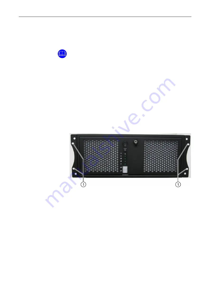
IDH computer front view:
1 Fastening
holes


