


Camera settings
30
Siemens AG
03.2011
9.2.9
CAMSET
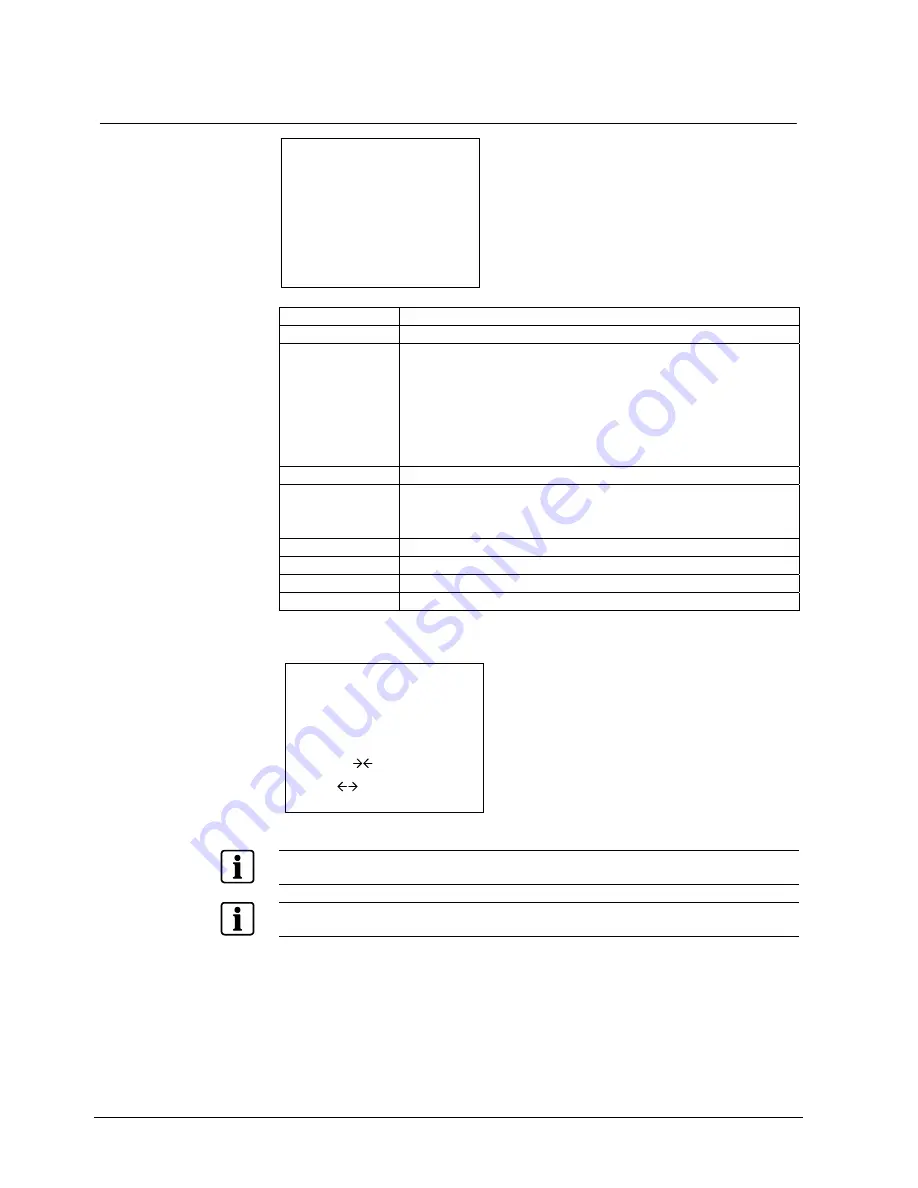
<CAMSET MENU>
CAM ID
BAUD RATE
PROTOCOL
DISP MODE
DISP ITEM
TITLE
ALARM TEXT
SAVE
END
CAM ID
Select camera ID: 1 – 255
BAUD RATE
Select serial communication speed: 2400/4800/9600/19200
PROTOCOL
Select operating protocol:
z
COMMAND: for factory use only
z
SIEMENS – B (Parity = Even)
z
SIEMENS – S (Parity = Even)
z
MOLYNX
(Parity = Even)
z
PELCO – D
(Parity = None)
z
PELCO – P
(Parity = None)
DISP MODE
Select OSD display mode: Off/Push On/On
DISP ITEM
Select display elements:
1: Camera title and camera number
2: Camera title, zoom factor and camera number
TITLE
Press ENTER to configure camera title
ALARM TEXT
Press ENTER to configure alarm text
SAVE
Press ENTER to save CAMSET configuration
END
Back to the next higher menu level
Move the cursor using the "Far/Near", "Tele/Wide" keys. Press the MENU key to
open a sub-menu.
TITLE TEXT
<TITLE MENU>
A B C D E F G H I J
K L M N O P Q R S T
U V W X Y Z 0 1 2 3
4 5 6 7 8 9 ( ) :
; . -
! < > ,
`
CMD
< > S E
CMD description
←
: One position to the left
→
: One position to the right
< : Deletes character at cursor position and
moves to the left
> : Deletes character at cursor position and
moves to the right
S : Save the present setting
E : Exit
If you make any changes in the
BPS
or
PROTOCOL
submenus, be sure to select
SAVE
PROTOCOL
& BPS
to save your changes.
Do not disconnect the camera from the power source while saving.