Instruction manual AQ101, AQ101D, AQ110P, AQ01
24 (48
)
3.2
AQ01
ARC FLASH SENSOR
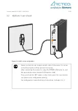
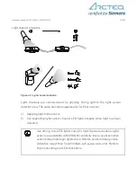
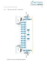
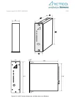
Figure 3-3: AQ01 sensor configuration
Sensor connectors are located at both ends of the sensor for series
connecting maximum three sensors in one line.
After connecting the sensor to relay, the ERROR LED turns on, and
the appropriate sensor channel LED starts to blink.
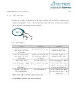
Press and hold the SET button on the front panel for 3 seconds to
run system auto-configuration setting.
See configuration related technical instructions in chapter 3.1.3.
Summary of Contents for Arcteq AQ01
Page 1: ...INSTRUCTION MANUAL AQ101 AQ101D AQ110P AQ01 ...
Page 44: ...Instruction manual AQ101 AQ101D AQ110P AQ01 44 48 ...
Page 45: ...Instruction manual AQ101 AQ101D AQ110P AQ01 45 48 ...
Page 46: ...Instruction manual AQ101 AQ101D AQ110P AQ01 46 48 9 2 AX001 CONNECTION FIBER ...
Page 47: ...Instruction manual AQ101 AQ101D AQ110P AQ01 47 48 9 3 AQ01 ARC FLASH SENSOR ...

