6 / 14
Siemens
Electromotive actuators for combi valves
CE1N4833en
Building Technologies
2017-11-15
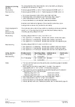
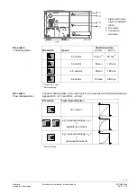
Blockade detection is always operational. In other words, the actuator
demonstrates the following response at end positions H
100
and H
0
not only during
initialization and calibration, but also during normal control operation:
1.
The actuator travels to the end position; the LED is lit in the direction of travel.
2. It detects the end position; both LEDs are lit green.
3.
It then briefly travels in the opposite direction; the LED is lit in the direction of travel.
4.
It then returns to the end position; LED is lit in the direction of travel
5.
It detects the end position; both LEDs are lit green.
This response is repeated with time intervals between travels increasing
exponentially. The intervals are:
25 seconds
1 min 40 seconds
6 min 40 seconds
26 min
1 h 46 min 40 seconds
7 h 6 min 40 seconds
1 day 4 h 26 min 40 seconds
for the previous interval.
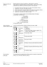
The status and acting direction indication consists of two green, lit LEDs.
Indication
Function
4
8
33
Z
08
ƒ
LED flashes
green
ƒ
LED flashes
green
ƒ
Initialization.
ƒ
Manual mode.
ƒ
Delay after operating voltage is supplied, or the
fail-safe function is triggered.
4
8
33
Z
09
ƒ
Steady green
ƒ
--
Actuator stem retracts.
4
8
33
Z
10
ƒ
--
ƒ
Steady green
Actuator stem extends.
4
8
33
Z
11
ƒ
Steady green
ƒ
Steady green
End position reached.
4
8
33
Z
12
ƒ
LED flashes
green
ƒ
--
Blockage or foreign object detected during retraction.
4
8
33
Z
13
ƒ
--
ƒ
LED flashes
green
Blockage or foreign object detected during extension.
4
8
33
Z
14
ƒ
--
ƒ
--
No operating voltage
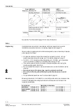
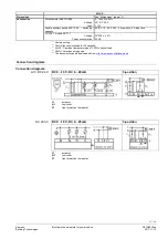
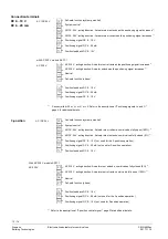
The actuators can be operated using a frost protection thermostat or temperature
detector, see "Connection diagrams", page 11.
Response at the end
positions
Status and acting
direction indication (LED)
Frost protection
thermostat.


