DESCRIPTION
1-14
Document No.: COM-00-05-16 June 2006, Revised June 2014
Version: C.1
1.9
J1/J2 JUMPER DETECT TEST FRAMES
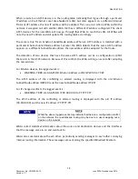
The test frames issued by the WAG’s boot monitor look something like the following:
:JT010232053192X:
When the operator has a computer plugged into the serial interface and the WAG starts testing
whether the J1/J2 jumpers are in place, the operator may see these test frames.
The jumper detection test frames start with :JT to indicate a Jumper Test. It’s followed by the IP
address of the WAG which is then followed by an
X:
to indicate the end of the test frame.
1.10
RS485 OPERATION
When the WAG is configured for RS485, the WAG also must be configured for one of the Genisys
ATCS protocols – Office if the WAG is to operate as a Bus Master or Field if the WAG is to operate
as a Bus Slave. There must be only one WAG Bus Master configured as Genisys ATCS Office.
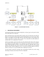
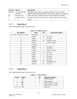
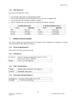
Figure 1-6 shows an example of a typical RS485 operational interconnection. Figures 1-7 and 1-8
show the RS485 cable interconnections used with this example, relying on the internal J1/J2
jumpers.
Figure 1-6.
RS485 Operational Interconnection


