5
11. Technical information.
11.1 Operating principle.
The cooling unit for electric enclosures works
on the basis of a refrigeration circuit consisting
of four main components: compressor, evapo-
rator, condenser and expansion device (figure
F.36.0
). The circuit is hermetically sealed and
the refrigerant circulates inside
it. The refriger-
ant used is R134a, chlorine free and harmless
for the ozone layer. The unit is divided into two
hermetically separated sections where the am-
bient air and enclosure air do not come into
contact with one another and are treated sepa-
rately. The compressor (CP) compresses the
refrigerant and takes it to a high pressure and
high temperature. The compressor then pushes
the refrigerant through a heat exchanger coil,
called condenser (C), where it is cooled by am-
bient air thus passing from the gas to the liquid
state. At the liquid state it then passes through
the capillary (EXP) and as it is at a much lower
pressure, nebulizes at the outlet. It is then re-
ceived by the heat exchanger coil, called
evaporator (E), by means of which it absorbs
heat from the enclosure air and passes from a
liquid state to gas. The enclosure is cooled
down in this manner. The gas is then drawn
back into the compressor and the above de-
scribed cycle is repeated.
11.2 Safety devices.
The refrigeration circuit is fitted with a high
pressure safety switch P (figure
F.36.0
) set at
maximum cooling unit working pressure. If the
threshold is exceeded, the pressure switch
stops the compressor working. It is the auto-
matically resettable type. The fans and com-
pressor have a thermal cut-out switch inside
that stops them in the case of anomalous over
temperatures.
11.3 Disposal.
Caution! The cooling unit contains R134a re-
frigerant and small quantities of lubricating
oil
. These substances pollute and must not be
dumped. Replacement, repairs and final dis-
posal must be seen to by experts.
NOTE
Keep the documentation in a dry place.
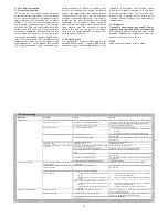
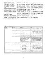
12. Troubleshooting
Malfunction
Conditions
Causes
Remedy
The temperature inside the enclosure is lower than
what is set on the adjustment thermostat.
This is not a malfunction of the cooling unit. To verify functioning
when testing, lower the thermostat setting until the compressor
and external fan start working and then reset the thermostat.
The internal fan works, the external fan and
compressor do not work.
The adjustment thermostat has failed
Change the adjustment thermostat
No component works
No electricity getting to the unit.
This is not a malfunction of the cooling unit.
•
Make sure the power cable has been connected well to the
terminals.
•
Check that the cubicle doors and switches are closed
Cooling unit empty of fluid
Call a refrigeration expert or the Manufacturer’s Technical Assis-
tance Service
Compressor, external and internal fan work
Compressor mechanical failure
Call a refrigeration expert or the Manufacturer’s Technical Assis-
tance Service
Internal fan capacitor failed
Change the internal fan’s capacitor
Compressor and external fan work, internal
fan does not work
Internal fan failed
Change the internal fan
Compressor’s amperometric protector failed (external
to the compressor, where present)
Change the amperometric protector
Relay or PTC for compressor starting failed
Change the relay or PTC for compressor starting
Capacitor for compressor starting failed (where pre-
sent)
Change the capacitor for compressor starting
Compressor motor electrical failure
Call a refrigeration expert or the Manufacturer’s Technical Assis-
tance Service
High pressure safety switch failed
Call a refrigeration expert or the Manufacturer’s Technical Assis-
tance Service
It fails to cool
External and internal fan work, compressor
does not work
Compressor contactor failed (where present)
Change the contactor
External and internal fans work, compressor
works all the time
Cooling unit under sized for the heat dissipated inside
the enclosure
Change the cooling unit with another of greater capacity
Inside fan works, external fan and compres-
sor work irregularly
Insufficient gas in the cooling unit
Call a refrigeration expert or the Manufacturer’s Technical Assis-
tance Service
High pressure safety switch triggered:
•
Ambient temperature over the maximum work-
ing limit
•
Heat exchanger coil (condenser) either dirty or
clogged
•
Ventilate the premises where the enclosure is installed to
keep ambient temperature lower.
•
Clean the exchanger with compressed air and detergent
It is not cooling enough
External and internal fans work, compressor
works irregularly
Thermal protector inside the compressor triggered:
•
Ambient temperature over the maximum work-
ing limit
•
Heat exchanger coil (condenser) either dirty or
clogged
•
Ventilate the premises where the enclosure is installed to
keep ambient temperature lower.
•
Clean the coil with compressed air and detergent
Enclosure door open
Too much ambient air inside the enclosure
This is not a malfunction of the cooling unit. Close the enclosure
door or disable the cooling unit
Enclosure protection level is below IP54
This is not a malfunction of the cooling unit. Seal enclosure open-
ings, e.g. for passage and upward path of wires
Too much condensate forming
Enclosure door closed
The enclosure/cooling unit connecting seal has been
fitted incorrectly
Check seal and remedy

