background image

7SR210 & 7SR220 Installation Guide 


Document Release History 


This document is issue 

2010/05.


2011/05 First 

issue 

Page 2 of 24 


©2011 Siemens Protection Devices Limited 

Summary of Contents for 7SR210 Argus

Page 1: ...ed nor shall any model or article be reproduced from this document unless Siemens Protection Devices Limited consent While the information and guidance given in this document is believed to be correct no liability shall be accepted for any loss or damage caused by any error or omission whether such error or omission is the result of negligence or any other cause Any and all such liability is discl...

Page 2: ...7SR210 7SR220 Installation Guide Document Release History This document is issue 2010 05 2011 05 First issue Page 2 of 24 2011 Siemens Protection Devices Limited ...

Page 3: ...ction Wiring Diagrams 13 5 1 Wiring Diagram 7SR21 OC EF Relay 13 5 2 Wiring Diagram 7SR22 Directional OC EF Relay 14 Section 6 Data Comms Connections 15 6 1 Standard RS485 Connections 15 6 2 IRIG B Connections 15 6 3 Additional Optional Fibre Optic Connections 16 6 4 Additional Optional RS485 Connections 17 6 5 Additional Optional RS232 Connections 17 6 6 Additional Optional Ethernet Connection fo...

Page 4: ...ure 5 1 1 Connection Diagram for 7SR21 Relay 13 Figure 5 2 1 Connection Diagram for 7SR22 Relay 14 Figure 6 1 1 RS485 Data Comms Connections Between Relays 15 Figure 6 3 1 Data Comms to Multiple Devices Using 7SG24 and F O Star Network 16 Figure 6 3 2 Data Comms to Multiple Devices Using 7SG24 and F O Ring Network 16 Figure 6 4 1 RS485 Data Comms Connections Between Relays 17 Figure 6 5 1 RS232 Da...

Page 5: ...n The relay uses a liquid crystal display LCD which is used in the programming and for operation The LCD has a vertical viewing angle of 30 and is back lit However the best viewing position is at eye level and this is particularly important given its control features The relay should be mounted on the circuit breaker or protection panel to allow the operator the best access to the relay functions ...

Page 6: ...fitted to relays these may present a danger of electric shock or burns if touched 2 3 Fibre Optic Communication Where fibre optic communication devices are fitted these should not be viewed directly Optical power meters should be used to determine the operation or signal level of the device 2 4 Front Cover The front cover provides additional securing of the relay element within the case The relay ...

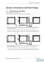
Page 7: ...FOR ETHERNET COMMS MODULE 70mm FOR F O COMMS CABLE 75 mm MIN CLEARANCE FOR ETHERNET COMMS WIRING Figure 3 1 1 Overall Dimensions mm and panel Drilling for Size E6 Epsilon case Typically 4 2 kg PANEL CUT OUT 168 182 201 5 159 9 75 SIDE VIEW 31 216 5 FRONT VIEW 207 5 177 151 5 NOTE THE 3 6 HOLES ARE FOR M4 THREAD FORMING TRILOBULAR SCREWS THESE ARE SUPPLIED AS STANDARD AND ARE SUITABLE FOR USE IN FE...

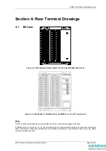
Page 8: ...d crimps with 90 bend are recommended 3 2 2 Panel Fixings Typical mounting screw kit per Relay Consists of 4 off M4x10mm Screws 4 off M4 Nuts 4 off M4 Lock Washer Typical rear terminal block fixing kit 1kit per terminal block fitted to relay Consists of 28 x M4 8mm Screws 28 x M4 Lock Washer 3 2 3 Fibre Optic Connectors The relay has Fibre Optic ST TM BFOC 2 5 bayonet connectors fitted when specif...

Page 9: ... O ST Connectors Notes 1 Recommended terminations are pre insulated must be crimped using approved tooling 2 RS485 block B terms 14 16 18 20 connections to this communication facility is by screened twisted pair cable On site when wiring other facilities ensure that these terminals are not obscured by other wiring runs Cable should be RS485 compliant 2011 Siemens Protection Devices Limited Page 9 ...

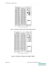
Page 10: ...R21 7SR22 Installation Guide Figure 4 1 3 E6 Standard Additional Comms IRIG B RS485 See Note 2 Figure 4 1 4 E6 Standard Additional Comms IRIG B RS232 Page 10 of 24 2011 Siemens Protection Devices Limited ...

Page 11: ...Standard Additional Comms IRIG B 2 x F O ST Connectors Notes 1 Recommended terminations are pre insulated must be crimped using approved tooling 2 RS485 block B terms 14 16 18 20 connections to this communication facility is by screened twisted pair cable On site when wiring other facilities ensure that these terminals are not obscured by other wiring runs Cable should be RS485 compliant ...

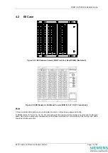
Page 12: ...d terminations are pre insulated must be crimped using approved tooling 2 RS485 block B terms 14 16 18 20 connections to this communication facility is by screened twisted pair cable On site when wiring other facilities ensure that these terminals are not obscured by other wiring runs Cable should be RS485 compliant Page 12 of 24 2011 Siemens Protection Devices Limited ...

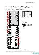
Page 13: ...210 7SR220 Installation Guide Section 5 Connection Wiring Diagrams 5 1 Wiring Diagram 7SR21 OC EF Relay Figure 5 1 1 Connection Diagram for 7SR21 Relay 2011 Siemens Protection Devices Limited Page 13 of 24 ...

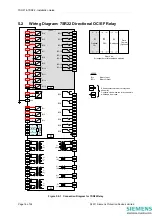
Page 14: ... 8 7 5 BO 9 11 9 BI 7 ve 12 BI 8 ve 14 BI 9 ve ve 16 18 BI 10 20 BI 11 ve 22 BI 12 ve 24 BI 13 ve ve 26 28 ve BO 10 15 13 21 19 17 BO 11 BO 12 27 25 23 BO 13 BO 14 1A 5A 1A 5A IL2 IB 1A 5A IL3 IC 1A 5A I4 IG 15 16 11 12 1A 5A I5 ISEF 3 4 7 8 A Analogue B PSU C Optional I O 1 2 27 28 1 2 1 2 27 28 27 28 Data Comms Optional Rear View Arrangement of terminals and modules B C A RS485 Screen B Term 14 ...

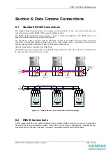
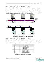
Page 15: ...RS485 bus The RS485 data communications link with a particular relay will be broken if the relay element is withdrawn from the case all other relays will still communicate A RS485 Screen B Term 14 16 18 20 RS 485 Twisted pair screened Cable To Control System To Control System 14 16 18 20 RS485 Screened twisted pair Rear terminals 14 16 18 14 16 18 RS485 Screened twisted pair Rear terminals Ext Wir...

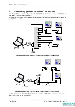
Page 16: ...res bend radii comply with the recommended minimum for the fibre used typically 50mm is acceptable Figure 6 3 1 Data Comms to Multiple Devices Using 7SG24 and F O Star Network Figure 6 3 2 Data Comms to Multiple Devices Using 7SG24 and F O Ring Network The F O data communications link with a particular relay will be broken if the relay element is withdrawn from the case all other relays will still...

Page 17: ...d pair screened Cable To Control System To Control System 14 16 18 20 RS485 Screened twisted pair Rear terminals 14 16 18 14 16 18 RS485 Screened twisted pair Rear terminals Ext Wire loop to Include line terminating Res A RS485 Screen B Term 14 16 18 20 A RS485 Screen B Term 14 16 18 20 Figure 6 4 1 RS485 Data Comms Connections Between Relays 6 5 Additional Optional RS232 Connections The additiona...

Page 18: ...al RJ45 connectors When installing fibre ensure that the fibres bend radii comply with the recommended minimum for the fibre used typically 50mm is acceptable 62 5 125μm glass fibre is recommended for all distances Figure 6 6 1 Ethernet connection for IEC 61850 star connection Figure 6 6 2 Ethernet connection for IEC 61850 ring connection Page 18 of 24 2011 Siemens Protection Devices Limited ...

Page 19: ...220 Installation Guide Section 7 Connection Diagrams 7 1 Typical Connection 7SR22 Directional OC EF and REF Figure 7 1 1 7SR22 Applied to Transformer Incomer 2011 Siemens Protection Devices Limited Page 19 of 24 ...

Page 20: ...R22 Installation Guide 7 2 Typical Connection 7SR22 Directional OC EF and NVD Figure 7 2 1 7SR22 Applied to Transformer Incomer Including HV NVD Protection Page 20 of 24 2011 Siemens Protection Devices Limited ...

Page 21: ... connections are typical only 3 Application shows use of V4 as an NVD input 4 Star Connected VT Phase Voltage Config Van Vbn Vcn IL1 IA 1 2 5 6 9 10 13 14 A 17 18 19 20 21 22 23 24 25 26 27 28 1A 5A 1A 5A 1A 5A 1A 5A 15 16 11 12 1A 5A 3 4 7 8 B C V4 VX VL3 VC VL2 VB VL1 VA IL2 IB IL3 IC I4 IG I5 ISEF Figure 7 3 1 7SR22 Applied to Feeder Including NVD Protection 2011 Siemens Protection Devices Limi...

Page 22: ...25 26 27 28 1A 5A 1A 5A 1A 5A 1A 5A 15 16 11 12 1A 5A 3 4 7 8 B C V4 VX VL3 VC VL2 VB VL1 VA IL2 IB IL3 IC I4 IG I5 ISEF NOTES 1 CT circuits are shown connected to 1A tap use alternative tap for 5A rated CTs 2 CT and Earth connections are typical only 3 Voltage Config Vab Vbc 3V0 Figure 7 4 1 7SR22 Applied to Feeder Page 22 of 24 2011 Siemens Protection Devices Limited ...

Page 23: ...B C V4 VX VL3 VC VL2 VB VL1 VA IL2 IB IL3 IC I4 IG I5 ISEF NOTES 1 CT circuits are shown connected to 1A tap use alternative tap for 5A rated CTs 2 CT and Earth connections are typical only 3 Vee Connected VT Phase Voltage Config VA VB VC 4 DEF elements must be NPS polarised Vo polarising not applicable Figure 7 5 1 7SR22 Applied to Feeder No Zero Sequence Voltage Source 2011 Siemens Protection De...

Page 24: ... VL2 VB VL1 VA IL2 IB IL3 IC I4 IG I5 ISEF NOTES 1 CT circuits are shown connected to 1A tap use alternative tap for 5A rated CTs 2 CT and Earth connections are typical only 3 Vee Connected VT Phase Voltage Config Va Vb Vc 4 DEF elements must be NPS polarised Vo polarising not applicable 5 V4 used for NVD input Capacitor Cones Adaptor Unit Figure 7 6 1 7SR22 Applied to Feeder with Capacitor Cones ...

Reviews: