background image


Siemens Protection Devices Limited     


                  3 


Summary of Contents for 7PG17-XR151

Page 1: ...Answers for energy 7PG17 XR 151 2 3 Supervision Relays Reyrolle Protection Devices ...

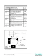
Page 2: ...auxil iary supply by removing fuses and links as necessary Physically check the wiring to the relay terminals for se curity and that is correct to the circuit schematic wiring diagrams Using a 500V insulation test set a Connect all relay terminals together and measure the resistance to earth b Connect the d c input terminals together and measure the resistance between these terminals and all other...

Page 3: ...Siemens Protection Devices Limited 3 ...

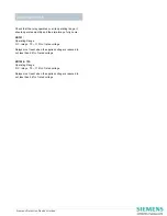
Page 4: ...ure go fully home XR151 Operating Range D C relays 70 115 of rated voltage Relays must reset when the applied voltage is reduced to not less than 26 of rated voltage XR152 153 Operating Range D C relays 70 115 of rated voltage Relays must reset when the applied voltage is reduced to not less than 26 of rated voltage Electrical Tests ...

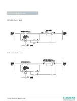
Page 5: ...Siemens Protection Devices Limited 5 XR151 with Self Reset Trip Relays XR151 with Latched Trip Relays Application Diagrams ...

Page 6: ...Siemens Protection Devices Limited 6 XR152 XR153 Please note These diagrams are for reference only the relay connection diagram for the specific device purchased should always be consulted ...

Page 7: ...49 180 524 70 00 Fax 49 180 524 24 71 Charges depending on provider E mail support energy siemens com Power Distribution Division Order No C53000 G7076 C60 1 Printed in Fürth Printed on elementary chlorine free bleached paper All rights reserved Trademarks mentioned in this document are the property of Siemens AG its affili ates or their respective owners Subject to change without prior notice The...

Reviews: