


Connecting-up
05.2005
6SE7087-2NP85-0AA0 Siemens
AG
7-6
Operating Instructions
SIMOVERT MASTERDRIVES
7.1.2
Power connections for 50 kW / 100 kW rectifier units
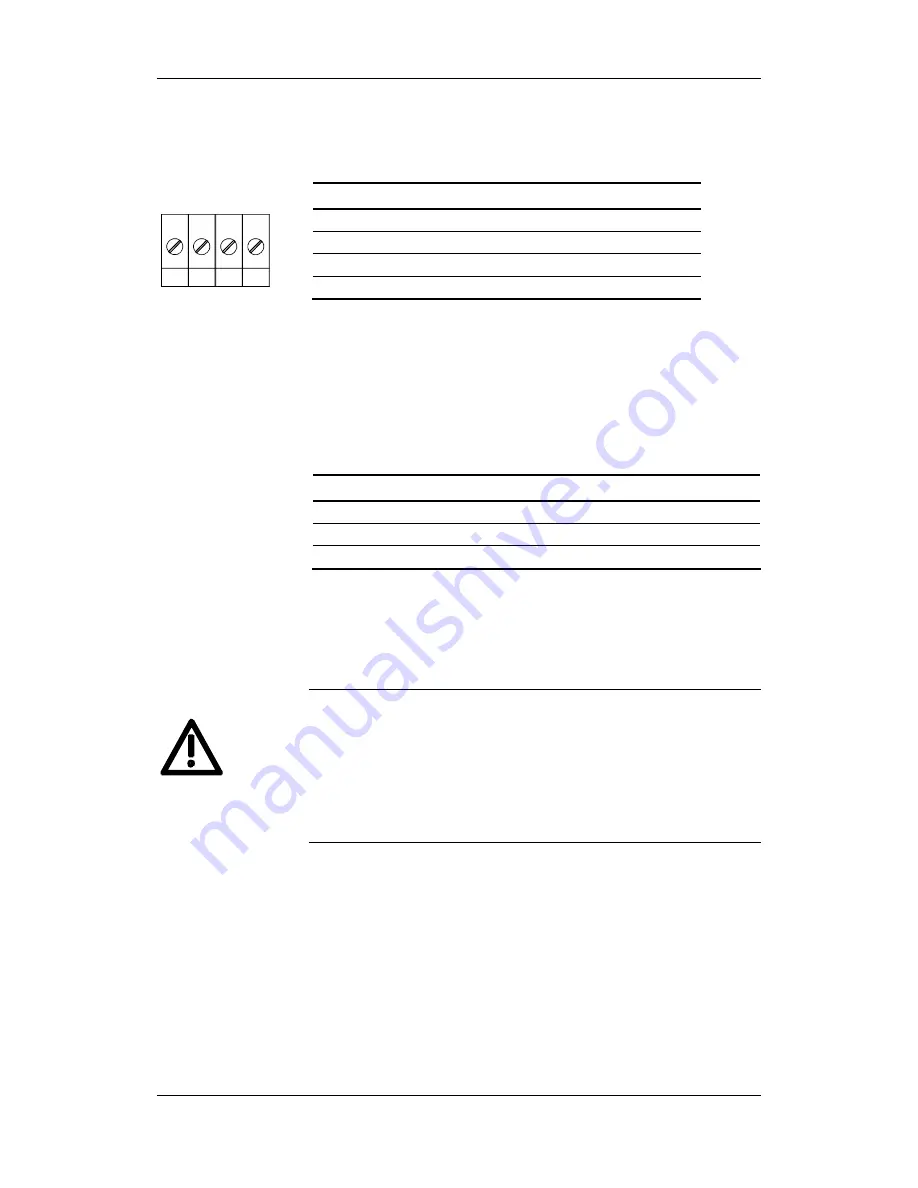
The mains connection is to a terminal block at the bottom of the unit.
Terminal Meaning
Range
PE
Protective conductor connection
3AC 380 - 480 V
U1 / L1
Phase U1 / L1
3AC 380 - 480 V
V1 / L2
Phase V1 / L2
3AC 380 - 480 V
W1 / L3
Phase W1 / L3
3AC 380 - 480 V
Connectable cross-section:
For 50 kW rectifier unit:
50 mm² (AWG 1/0)
For 100 kW rectifier unit: 95 mm² (AWG 4/0)
Terminal PE is at left as viewed from the front.
Table 7-4
Mains connection
The purpose of the DC link bus module is to supply the connected
inverters with the generated direct voltage.
Bar Designation
Meaning
Range
3
PE3
Protective conductor connection
2
D / L-
DC link voltage -
DC 510 - 650 V
1
C / L+
DC link v
DC 510 - 650 V
Connectable cross-section: “Electro-plated copper" 3x10 mm, rounded
off according to DIN 46433.
Bar 1 is at the front when installed.
Table 7-5
DC link bus module
The current carrying capacity of the copper bars is 120 A.
The 100 kW feeder supplies 230 A and would overload the copper
bars. It is therefore provided with 2 busbar connections with a current
carrying capacity of 120 A each. These take the power to busbars on
the right and left of the rectifier unit. The current distribution is not
monitored. Measures must therefore be taken at the planning stage to
ensure that the current fed to each busbar does not exceed the
specified maximum.
X1 – Mains
connection
PE
U1
V1
W1
X3 - DC link bus
module
DANGER


