


s
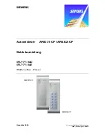
Operating instructions card reader AR6331-CP / AR6332-CP
Page
11
from
36
Order no.: A24205-A335-H050
GB
5 Setting
up
5.1
Connecting the reader
The reader is connected using the terminal strip (see: “Figure 4: Electronic board”) of the
reader mounted into the top section of the housing.
Connector for keypad type AR6332-CP
Switches for adress
- + A B
Figure 4: Electronic board, connectors
Terminal
Function
Strip
Description
AR633x-CP card reader
-
Power supply 0 volt DC
+
Power 12 volt DC
A
RS485 - A
B
RS485 - B
Connector positions from left to right (top view)
Table 1: Terminal allocation on the terminal board