GAMMA
instabus
Technical product information
June 2010
Switching actuator, main module N 513/11
5WG1 513-1AB11
3x AC 230/400V, 20AX, C-load, load-check
Technical manual
N 513/11, 6 pages
Siemens AG
Industry Sector, Building Technologies
Update: http://www.siemens.com/gamma
© Siemens AG 2010
Low Voltage Distribution
Subject to change without further notice
P.O. Box 10 09 53, D-93009 Regensburg
2.4.3.6/2
output individually which switching state it is to assume
on a bus voltage failure and after the bus voltage recov-
ery: as before bus voltage failure, ON or OFF.
Application program
The N 513/11 switching actuator needs the application
program "07B0 A15 Switching Actuator 981B02". This
controls the outputs of the main module as well as the
outputs of all connected submodules via their 6-pole
interface.
In bus mode, a communication object can be available
for each actuator output - for switching, for manual
override, for a forced control, for a logical combination
and for status query. Furthermore, if required, time-
limited switching instead of permanent switching on can
be enabled for each channel via an optional "Night
mode" object (e.g. for lighting while cleaning), if need be
with a warning before switching off by multiple switch-
ing the output on and off (flashing). It can also be se-
lected whether all a module's outputs are to be set jointly
and thus identically or whether each output is to be set
separately and individually.
Amongst others, the application program includes op-
tional detection and monitoring of the load current for
each output on load failure and/or overload, simultane-
ous switching of all 3 outputs (3-phase switching), con-
version of a speed given as a percentage value into 1- to
3-stage switching commands (fan speed control), con-
version of a valve setting given as a percentage value
into a pulse width modulated (PWM) switching com-
mand (thermal drive control), a switching cycle and
operating hours count with threshold monitoring for
each output and an integrated 8-bit scene control, in
which each output can be incorporated into up to 8 sce-
nes.
To load the application program, the Engineering Tool
Software (ETS) is required as version 3.0 f or higher.
Note: If the N 513/11 application program is "unloaded"
with the ETS, then you will no longer be able to activate
direct mode, i.e. the LED status display and local switch-
ing of the outputs using the buttons on the front panel
of the actuator are disabled. Only after reloading the
application program can you re-enable the status display
and direct mode.
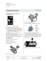
Connection example
Figure 1. Connection example
Installation notes
•
The device can be used for permanent installation in
dry interior rooms and for insertion in distribution
boards or miniature housings.
V
DANGER
•
The device must be mounted and commissioned by an
authorised electrician.
•
When connecting the device, it should be ensured that
the device can be isolated.
•
The device must not be opened.
•
For planning and construction of electric installations,
the relevant guidelines, regulations and standards of
the respective country are to be considered.
•
With the last sub-module no bridging connector must
be plugged into the jack for a further sub-module on
the right sub-module side.


