4 / 10
Bestell-Nr. / Order No.: 3ZW1012-1VL00-3AA0
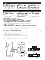
DANGER
PELIGRO
DANGER
Hazardous voltage.
Will cause death or serious injury.
Turn off and lock out all power supplying
this device before working on this device.
Replace all covers before power
supplying this device is turned on.
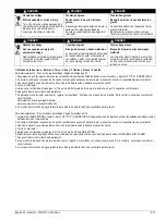
Tensión peligrosa.
Puede causar la muerte o lesiones
graves.
Desenergice totalmente antes de instalar o
darle servicio. Reemplace todas las
barreras y cubiertas antes de energizar el
interruptor.
Tension dangereuse.
Danger de mort ou risque de blessures
graves.
Couper l'alimentation de l'appareil et barrer
avant de travailler.
Remplacez touts les couverts avant que
l'approvisionnement de pouvoir soit alimenté.
!
!
!
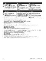
DANGER
PELIGRO
DANGER
Hazardous voltage.
Can cause personal injury and
equipment damage.
Neutral Sensor terminals must be properly
connected or shorted together before
energizing the circuit.
Tensión peligrosa.
Riesgo de lesiones y daños materiales.
Los bornes del transformador de intensidad
del neutro deberán estar correctamente
conectados o estar cortocircuitados antes
de la puesta bajo tensión del circuito.
Tension dangereuse.
Risque de blessures et de dommages
matériels.
Les bornes du transformateur de courant de
neutre doivent être raccordées correctement
ou être court-circuitées avant la mise sous
tension du circuit.
!
!
!
OPERATION TESTING
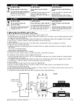
A. GROUND FAULT RESIDUAL METHOD - 3 Phase / 3 Wire
For circuit breakers with “G“, "V" or "W" in the catalog number. Reference page 2/10.
1. Set all trip unit settings to their maximum setting and on Model 586 trip units set GF TYPE = GND RESIDUAL.
2. The supplied neutral sensor wiring should be left with wires shorted together. Bundle the wires where convenient during the test.
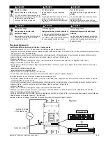
3. Using Figure 1, connect a low voltage current source to the circuit breaker phase A.
4. Close the circuit breaker.
5. Apply a test current equal to 125 percent of the ground fault pickup setting for a maximum of 10 seconds.
6. Turn off the low voltage current source.
7. Verify that the circuit breaker tripped and then record the results. Proceed to step 8, if tripped, otherwise contact technical support:
www.siemens.com/lowvoltage/manuals
www.usa.siemens.com/powerdistribution
8. Repeat steps 3– 7 for circuit breaker phases B and C.
9. Testing is completed. Turn off the low voltage current source and disconnect from circuit breaker.
For circuit breakers with “K“ in the catalog number. Reference page 2/10.
1. Set the GF ALARM SETTING to the minimum setting and GF TYPE = GND RESIDUAL. Set all other trip unit settings to their maximum setting.
2. The supplied neutral sensor wiring should be left with wires shorted together. Bundle the wires where convenient during the test.
3. Using Figure 1, connect a low voltage current source to the circuit breaker phase A.
4. Close the circuit breaker.
5. Apply a test current equal to 125 percent of the GF ALARM SETTING.
6. While the test current is on, verify the trip unit LCD screen shows GROUND FAULT ALARM.
7. Turn off the low voltage current source.
8. If GROUND FAULT ALARM was displayed, record the results and proceed to step 9, otherwise contact technical support.
9. Repeat steps 3– 8 for circuit breaker phases B and C.
10.Testing is completed. Turn off the low voltage current source and disconnect from circuit breaker.
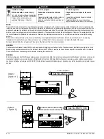
Model 555
+
Model 586
Low Voltage A.C.
Current Source
Neutral Sensor wires
Figure 1

