

3 / 10
Bestell-Nr. / Order No.: 3ZW1012-1VL00-3AA0
1
NEMA PB 2.2 is available from: National
Electrical Manufacturers Association
1300 N. 17
TH
Street, Suite 1847
Rosslyn, Va. 22209
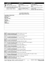
Table 1
( Reference table for test procedures B & C below )
1200A
1600A
800A
1000A
1200A
600A
800A
600A
400A
250A
400A
100A
150A
250A
60A
100A
150A
Trip Unit Rating
[ Rango de unidad de
disparo ]
NGSP120
NGSP160
PG
NGSN800
NGSP120
NGSP120
NG
NGSM600
NGSN800
MG
NGSM600
LG
NGSL400
LG
NGSJ250
NGSL400
JG
NGSF100
NGSF150
NGSJ250
FG
NGSD060
NGSF100
NGSF150
DG
Neutral Catalog No.
[ Numero de catalogo del
neutral ]
Frame
[ Caja
Base ]
Neutral Sensor
[ Sensor Neutral ]
1200A
1600A
800A
1000A
1200A
600A
800A
600A
400A
250A
400A
100A
150A
250A
60A
100A
150A
Trip Unit Rating
[ Rango de unidad de
disparo ]
NGSP120
NGSP160
PG
NGSN800
NGSP120
NGSP120
NG
NGSM600
NGSN800
MG
NGSM600
LG
NGSL400
LG
NGSJ250
NGSL400
JG
NGSF100
NGSF150
NGSJ250
FG
NGSD060
NGSF100
NGSF150
DG
Neutral Catalog No.
[ Numero de catalogo del
neutral ]
Frame
[ Caja
Base ]
Neutral Sensor
[ Sensor Neutral ]
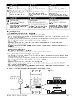
Instrucciones Generales:
IMPORTANTE: El sistema debe ser verificado para determinar que no exista acceso a tierra que podría crear un puente al Sensor.
1. Estos interruptores podrían ser ajustados para diferentes modos de operación, residual o retorno a tierra, como es descrito en las instrucciones
proveídas con el interruptor. Para mas información de aplicaciones, refiérase a la publicación de estándares NEMA No PB 2.2 - 1999 (R2004,
R2009) Application Guide For Ground Fault Protective Devices for Equipment.
1
2. Los parámetros de falla tierra para las unidades de disparo modelo 555 son ajustables y para falla a tierra residual solamente.
3. Los parámetros de falla a tierra para las unidades de disparo modelo 586 son ajustables y configurables para falla a tierra residual o método de
retorno a tierra. Refiérase a las instrucciones 3ZW1012-0VL02-2AA0 en como configurar los ajustes del LCD.
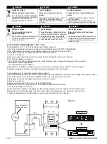
4. Cuando sea usado, el sensor neutral debe ser localizado adecuadamente alrededor del apropiado conductor del interruptor a proteger.
5. La polaridad de las conexiones del sensor neutral debe estar de acuerdo con la orientación mostrada en las instrucciones de instalación para
proveer una operación adecuada.
6. Una prueba simulada debe ser conducida usando una fuente de alta corriente y baja tensión. La intención de esta prueba no es la de verificar
los ajustes de protección de la falla a tierra, pero para verificar el propio funcionamiento.
7. Los resultados de la prueba deben registrarse en la forma proveída al final de este documento o en otra forma apropiada y debe estar disponible
para las autoridades de inspección.
8. For questions on performing ground fault performance tests, contact technical support at:
www.siemens.com/lowvoltage/manuals
www.usa.siemens.com/powerdistribution.
9. Basado en el método de instalación, realícese el procedimiento de prueba de operación A, B, o C indicado abajo.
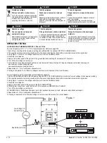
GENERAL INFORMATION:
IMPORTANT: The system shall be verified to determine that ground paths do not exist that would bypass the Sensor.
1. Some breakers may be set for different modes of operation, Residual or Ground Return - others are only Residual. For further information on
applications, refer to the NEMA standards publication No. PB 2.2 - 1999 (R2004, R2009) Application Guide For Ground Fault Protective Devices
for Equipment.
1
2. The ground fault settings for the Model 555 trip units are adjustable and ground fault residual method only.
3. The ground fault settings for the Model 586 trip units are adjustable and configurable for ground fault residual or ground return method. Refer to
the instructions 3ZW1012-0VL02-2AA0 on how to configure the LCD settings.
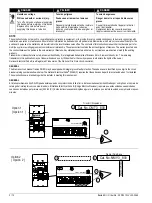
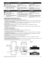
4. When used, the neutral sensor must be properly located around the appropriate conductor of the circuit to be protected.
5. The polarity of the neutral sensor connections must agree with the orientation shown in the installation instructions to provide proper operation.
6. A simulated test is to be done using a low voltage, high current source. This test is not intended to verify the calibration of the ground fault
protection but to verify it is properly functioning.
7. The test results should be recorded on the form provided at the end of this document or on other appropriate forms and should be available to the
inspection authority.
8. For questions on performing ground fault performance tests, contact technical support at:
www.siemens.com/lowvoltage/manuals
www.usa.siemens.com/powerdistribution.
9. Based on the installation method, perform operation test procedure A, B, or C below.


