5 – 8
3ZW1012-0WL11-0AB1
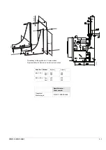
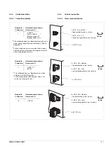
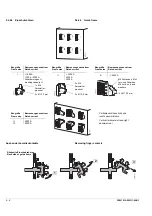
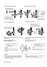
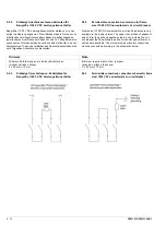
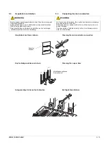
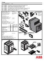
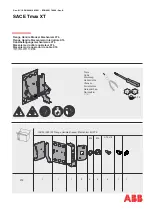
5.2.4.2 Guide frame
Removing finger contacts
5.2.4.2 Einschubrahmen
Ausbau der Lamellenkontakte
II
III
≤
5000 A
≤
2000 A
2500 A
3200 A
Baugröße
Frame size
Bemessungsnennstrom
Rated current
Baugröße
Frame size
Bemessungsnennstrom
Rated current
Baugröße
Frame size
Bemessungsnennstrom
Rated current
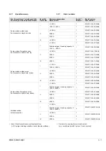
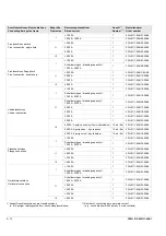
2 x Ø 13,5 mm
3 x Ø 13,5 mm
4 x Ø 13,5 mm
≤
1000 A,
1200 A - 2000 A
Schaltvermögen H
breaking capacity H
M6 Schrauben, Mut-
tern und Scheiben
M6 bolts, nuts and
washers
2 x M 6
Setzmutter
press nut
1 x M 6
Setzmutter
press nut
I
II
III
Vertikalanschlüsse links und
rechts asymmetrisch
Vertical terminals left and right
asymmetrical
Baugröße
Frame size
Bemessungsnennstrom
Rated current
4000 A
6300 A
1
2
3
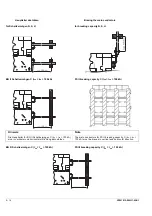
Rückseite Einschubrahmen
Back side of guide frame
Summary of Contents for 3ZW1012-0WL11-0AB1
Page 15: ...3ZW1012 0WL11 0AB1 0 XV ...
Page 87: ...3ZW1012 0WL11 0AB1 8 15 S Auslösung I Auslösung S tripping I tripping ...
Page 88: ...8 16 3ZW1012 0WL11 0AB1 Erdschlussauslösung Ground fault tripping ...
Page 359: ...3ZW1012 0WL11 0AB1 27 5 ...
Page 360: ...27 6 3ZW1012 0WL11 0AB1 ...
Page 366: ......
Page 367: ......


