Communication System Manual
3WN6 Circuit-Breakers
Version 1.0 (05/98)
Copyright Siemens AG 1998. All rights reserved.
31
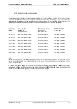
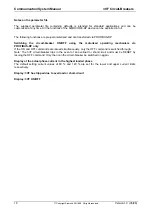
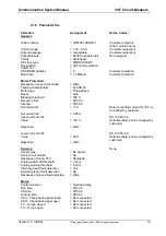
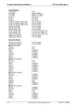
3.3 Procedure for connection to communication system
3WN6 is connected to PROFIBUS-DP in 8 steps:
11
Step 1:
Check that all the system components are fitted
Step 2:
Check the system requirements
Step 3:
Connect DP/3WN6 to PROFIBUS-DP
Step 4:
Connect DP/3WN6 to 3WN6
Step 5:
Connect DP/3WN6 to voltage supply
Step 6:
Bus configuration
Step 7:
Set bus address on DP/3WN6 interface module
Step 8:
Programming of bus master and data visualization
Step 1: Check that all the system components are fitted
Check that all the following system components are fitted before connecting 3WN6 to
PROFIBUS-DP: (cf. section 3.1.1, page 26):
Communication-capable 3WN6 circuit-breaker
DP/3WN6 interface module and connecting cable from interface module to circuit-breaker (supplied
with DP/3WN6)
Connector (6ES7) including terminating resistor for connecting interface module to PROFIBUS-DP
24 V DC voltage supply (DIN 19240)
Diskette with type or GSD file (supplied with DP/3WN6)
Software with standard software block
Programming device PG ... (for SIMATIC S5/S7, or other appropriate hardware)
COM-PROFIBUS software (for SIMATIC S5, or other appropriate software)
Step 2: Check the system requirements
The second step involves checking the following three requirements for connecting 3WN6 to
PROFIBUS-DP:
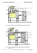
The communication-capable 3WN6 circuit-breaker must be installed and wired in accordance with
the user guide.
(When testing a draw-out circuit-breaker, this should be in the test position. For normal operation, it
should be in the connected position). When wiring, please ensure that the jumper arrangements on
the auxiliary connectors are correct (cf. Fig. 5, page 32 and Fig. 6, page 32).
The PROFIBUS-DP master must be present and operational.
11
This procedure must be performed for each individual 3WN6 circuit-breaker.

