


Description
16
9229 0106 176 0-
2020-09-18
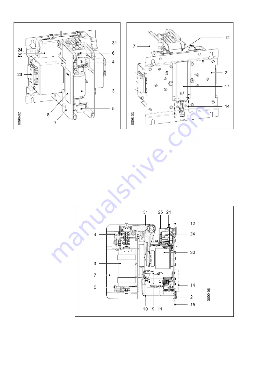
Fig. 7
Sectional view with mechanical closing latching, with shunt release Y1
and manual unlatching – CLOSED switch position
Fig. 5
Front view – high-voltage side, 1-pole
Fig. 6
Rear view – mounting side, 1-pole
2
Base plate (mounting)
3
Vacuum interrupter
4
Upper terminal
5
Lower terminal
6
Position indicator (CLOSED – OPEN)
7
Pole shell
8
Name plate
9
Mechanical closing latching with shunt release Y1 (optional)
10
Cover for closing latching (optional)
11
Shunt release Y1 (optional)
12
Push rod for manual unlatching (optional)
14
Unlatching (EMERGENCY STOP), manual (optional)
15
Draw bar for manual unlatching (optional)
17
Cover of the manual unlatching
21
Connector for supply voltage A1/A2
23
Auxiliary switch
24
Electronic controller
25
Cover hood of the electronic controller
30
Operating mechanism solenoid
31
Operating mechanism lever
Summary of Contents for 3TM
Page 12: ...Transport storage packaging 12 9229 0106 176 0 2020 09 18 Blank page ...
Page 26: ...Description 26 9229 0106 176 0 2020 09 18 Blank page ...
Page 36: ...Installation 36 9229 0106 176 0 2020 09 18 Blank page ...
Page 48: ...Maintenance 48 9229 0106 176 0 2020 09 18 Blank page ...
Page 50: ...Index 50 9229 0106 176 0 2020 09 18 Blank page ...


