SVENSKA
82
610.40 700.21
Siemens AG
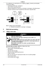
Bild 5 Kopplingar
5.2
Kontaktutförande
Effektkontakt
1. Använd kontakt storlek 1 eller storlek 1,5.
2. Montera kontakter enligt Bild 5. Anslut skyddsledare.
3. Anslut broms genom effektkontakt enligt Bild 5.
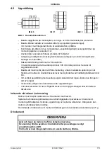
OBSERVERA
Felaktig ändring av kontaktens anslutningsriktning leder till skador på
anslutningskablarna.
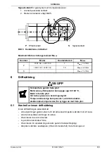
Överskrid inte tillåtna vridningsmoment enligt Bild 6
Endast maximalt 10 ändringar fram till ändläge av kontaktens anslutningsriktning,
med ditsatta passande motkontakter, är tillåtet.
Signal connections
Power connections
1FK7 02. - 1FK7 100
1FK7 101 / 1FK7 103
V
U
BR
W
BR2
5
4
2
1
6
GNYE
R1
S2
S4
S1
R3
S3
1
3
4
11
5
6
12
7
8
9
10
2
- Temp
+ Temp
not
connected
not
connected
not
connected
not
conn.
Resolver
Incremental Encoder
sin/cos 1 V
PP
+ Data
not
conn.
not
conn.
not
connected
M-Encoder
+ Temp
- Temp
+ Clock
0V Sense
- Clock
A -
A +
B -
B +
P-Encoder
5V Sense
1
3
4
11
5
6
13
7
8
9
10
2
12
14
15
16
17
- Data
L1
L2
L3
3
3
U
V
W
U2
V2
W2
Supply
Motor
BR
GNYE
BR2
V
W
U
Connector size 1
Connector size 1,5
Encoder
BR
(+)
BR2
(-)
U V W
3
M
Motor
Brake
Simple Absolute Encoder
Absolute Encoder
C -
M-Encoder
(0V)
+ Temp
- Temp
C +
0V
Sense
D -
R +
R -
D +
A -
A +
B -
B +
P-Encoder
(5V)
5V
Sense
1
3
4
11
5
6
13
7
8
9
10
2
12
14
15
16
E
not
conn.


