


Type WL Low Voltage Metal-Enclosed Switchgear
Electrical Connections
20
Hardware Tightening Instructions
All bus joint hardware furnished is zinc-plated, dichromate
treated, high strength steel. Cap screws are 1/2-13 SAE Grade
5, while nuts are SAE Grade 2. Sizes and grades other than
these are not to be used. Refer to
Figure 19
for required hard-
ware torque values. When purchaser’s specifications require,
special hardware (e.g., stainless steel) may be provided. For
such applications, consult the factory for proper torque range.
Torque hardware as described above. Do not exceed the maxi-
mum torque value given. Forces within the torque range will
produce a low resistance joint, without cold flow of material
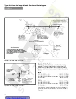
Connection to Power Transformer
Before making the primary connections to a liquid transformer,
it will be necessary to remove the transition box cover for access.
See
Figure 21.
The joints connecting power transformers to the
switchgear are the same as joints previously described, except
that braided flexible connectors are used to make certain that
strain transmitted to the transformer bushings is minimal and
as an aid to alignment. See
Figure 20.
Connections to dry type
transformers are normally made within the transformer enclosure.
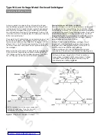
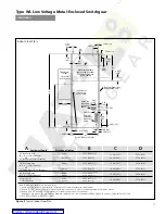
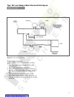
Figure 19.
Torque Values
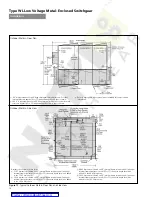
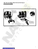
Figure 20.
Transformer Throat Connection (Lower Bus Shown,
Upper Bus Similar)
Transformer connector arrangements are shipped with flexible
connectors attached to either the switchgear assembly or the
transformer assembly. The flexible connectors contain the
required hardware to make the connections to the transformer
terminals. Carefully observe how the flexible connectors are
mounted to the switchgear (placement of bolts, nuts, washers
and spacers) then remove the flexible connectors or carefully
spread them to prevent damage to the transformer terminals
or connectors while the switchgear is brought into final posi-
tion. Carefully connect the flexible connectors to the trans-
former and switchgear terminals, and torque all connections.
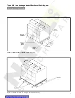
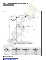
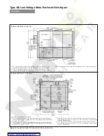
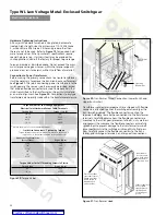
Figure 21.
Transformer Hood
Torque Values for Low Voltage Equipment
Electrical Joint Hardware Except Cable Terminals
Thread Size
Torque
(Lb-Ft)
1/4-20
6-9
3/8-16
20-30
M10
40-50
1/2-1340-50
Hex Socket Set Screw Size
(Across Flats)
Torque (Lb-In)
7/32”
150
1/4”
200
5/16”
275
3/8”
375
1/2”
500
9/16”
600
Field Wire Connectors - Tightening Torque
Torque all wire connectors, where not marked on the device or
component, to the values indicated in the table below
Torque Values for Self-Threading Screws In Plastic
Thread Size
Torque (Lb-In)
#8
10-12
1/4-14
45-55
Values shown are for non lubricated threads.
Transition Phase Bus
Transformer
Flange
Transition
Neutral Bus
Flexible Connectors
Trim cover slides
over transformer
flange, overlaps
and is bolted to
transition box
on both sides.
Removable
access covers
on both sides
are bolted to
transition box.
Indoor transition
box to liquid
transformer on
left hand end
of switchgear
group.


