background image

IV394E Rev. 00 

Installation and user manual 

Date of issue:


2015-12-11 

Pag. 14 di 34 + FR 


              Fig.29

φ

Parallel setting               


1.5.4 Rear panel instruction 
1.5.4.1 6 kVA H/S rear panel 


Fig.1-4 Rear Instruction 

1.  Parallel slot 

2.  Maintenance bypass switch (covered) 

3.  Intelligent slot 

4.  EPO 

5.  COM 

6(77,1*

3DUDOOHOVHW

,'

3DPRXQW

35HGXQG

Summary of Contents for Green Point

Page 1: ...IV394E Rev 00 Installation and user manual Date of issue 2015 11 19 Pag 0 di 34 FR 6 10 kVA UPS INSTALLATION AND USER MANUAL Green Point KEEP FOR FUTURE REFERENCE for the entire life of the appliance...

Page 2: ......

Page 3: ...ngle phase in single phase out high frequency online UPS designed by our R D team who is with years of designing experiences on UPS With excellent electrical performance perfect intelligent monitoring...

Page 4: ...ed even if the UPS input is not connected to the utility 2 Do disconnect the UPS input and make sure the UPS is complete off before moving the UPS or reconfigurate the connection otherwise there will...

Page 5: ...should be done by authorized technician 9 Keep the UPS in a dry area or environment if it will not be free of operation for long time Storage temperature of UPS with internal battery is 20 55 extende...

Page 6: ...2 Installation 17 2 3 Connection of parallel system 19 3 Operation 20 3 1 Working modes 20 3 1 1 AC mode 20 3 1 2 Bypass mode 20 3 1 3 Battery mode 20 3 1 4 ECO mode 21 3 2 Operation 21 3 2 1 Power o...

Page 7: ...an maintenance 25 4 2 Battery maintenance 25 4 3 Visual checking 25 4 4 UPS status checking 26 4 5 Function checking 26 5 Trouble shooting 26 Appendix 1 USB communication 28 Appendix 2 RS232 communica...

Page 8: ...can be used for computer center network management center auto control system telecom systems etc 1 2 Product range Capacity 6kVA 10kVA Model 6kVA S 6 kVA H 10kVA S 10kVA H Remarks with internal batte...

Page 9: ...ontrol high reliability self diagnostics and protections are featured n Intelligent battery management which extends battery life n LCD panel and LED indicators clearly indicate the system status and...

Page 10: ...rmation function setting information n LCD control panel 1 Five green LED and one red LED 2 LCD control panel which can display four line of English 3 Button On Off ESC Enter and Left Right 21 2FF 6 E...

Page 11: ...put n LCD display content 1 Running parameters Input voltage frequency output voltage frequency current loading output power inverter voltage battery voltage battery remaining capacity Bus voltage bus...

Page 12: ...and go to previous menu Turn to another menu or parameter Turn to another menu or parameter n UPS Messages reference table Explanation Content Initialization CurState Init No output No Out At bypass...

Page 13: ...n it will change to main menu see Fig3 Fig 3 Main menu 4 An arrow icon will come out on the LCD when pressing the ENT then the data info status info setting info can be selected by pressing the right...

Page 14: ...Fig 13 to 14 Fig 13 main menu Fig 14 main menu 7 Select and confirm setting menu setting information will be displayed on the screen which includes user set system set parallel set battery sett revis...

Page 15: ...e 2015 12 11 Pag 14 di 34 FR Fig 29 Parallel setting 1 5 4 Rear panel instruction 1 5 4 1 6 kVA H S rear panel Fig 1 4 Rear Instruction 1 Parallel slot 2 Maintenance bypass switch covered 3 Intelligen...

Page 16: ...15 12 11 Pag 15 di 34 FR 6 USB 7 Input switch 8 Input output battery terminal covered 1 5 4 2 10 kVA H S rear panel 1 Parallel slot 2 Maintenance bypass switch covered 3 Intelligent slot 4 EPO 5 COM 6...

Page 17: ...UPS located in the front panel and the bottom part so as to keep the ventilation in good conditions avoid temperature of components inside getting high Keep the UPS away from high temperature water f...

Page 18: ...ery voltage should be around 192 216 240Vdc measure positive and negative battery voltage should be around 96 108 120Vdc Don t mix batteries with different capacity manufacturers and don t mix brand n...

Page 19: ...les 1 USB cable provided in accessories can be used to connect the UPS with PC 2 Follow steps below to install SNMP if purchased A Remove the cover of SNMP slot at UPS rear panel and keep it for furth...

Page 20: ...the UPS are connected in parallel the copper wires required to connect with each UPS is minimum 10AWG for the 6KVA and 8AWG for 10KVA but the main wire for linking all the UPS in parallel should be N...

Page 21: ...mode and no power will be supplied to the loads 3 1 3 Battery mode In AC mode if the AC is absent or beyond normal range the rectifier and charger will stop working the loads will be powered by batte...

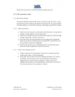
Page 22: ...pin and the system will execute self diagnostics After the self diagnostics is finished the buzzer inside will beep twice The system will go to bypass mode then AC and bypass indicators on front panel...

Page 23: ...hold for 1 second until hearing one beep battery and inverter indicators will be on after finishing self diagnostics The UPS will beep once every 3 seconds which means it is working in battery mode 2...

Page 24: ...3 2 Normal mode to battery mode The UPS will go to battery mode if the AC is failed The UPS will shut down automatically if batteries are drained When AC recovers the UPS will start the inverter autom...

Page 25: ...settings interface press ESC to return to main menu 3 Parameter which has been selected and to be changed will be highlighted Press arrow button to change the value and press ENT to confirm the value...

Page 26: ...d so as to keep battery in good conditions 1 The most proper working temperature is 15 to 25 Celsius degree 2 Avoid small discharging current Don t let UPS work in battery mode continuously for 24 hou...

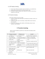
Page 27: ...ting Please contact the distributor if problems can not be solved by following trouble shooting below No Problem description Probable causes Solution 1 No display on LCD no self diagnose A Input power...

Page 28: ...then test the backup time again B Contact distributor to replace battery 10 Long beeps fault indicator on the LCD shows over temperature Over temperature inside UPS A Check to see if there is wind bl...

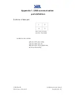
Page 29: ...2015 12 11 Pag 28 di 34 FR Appendix 1 USB communication port definition Definition of Male port Pin 1 VCC Pin 2 D pin 3 D Pin 4 GND Available function of USB Monitor UPS power status Monitor UPS alarm...

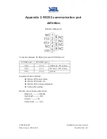
Page 30: ...PC RS232 port and UPS RS232 port PC RS232 port UPS RS232 port Pin 2 Pin 2 UPS send PC receive Pin 3 Pin 3 PC send UPS receive Pin 5 Pin 5 ground Available function of RS232 Monitor UPS power status M...

Page 31: ...45 default 45 Bypass frequency range 1 2 4 5 10 THDI 3 100 linear load input THDV 1 5 100 non liner load input THDV 1 battery Battery number 16 18 20pcs can be set Battery type VRLA Charge model Boost...

Page 32: ...ut voltage 320Vac 1Hr EMI Conduction IEC 62040 2 Radiation IEC 62040 2 Harmonics IEC 62040 2 EMS IEC 62040 2 MTBF 250 000Hr 1 1 400 000Hr MTTR 30min Isolation resistance 2M 500Vdc Isolation intension...

Page 33: ...IV394E Rev 00 Installation and user manual Date of issue 2015 12 11 Pag 32 di 34 FR Appendix 4 Options 1 Dry contact card 2 SNMP card 3 Parallel card...

Page 34: ...ly Fault LED lit 2 Inverter fault Including Inverter bridge is shorted Beep continuously Fault LED lit 3 Inverter Thyristor short Beep continuously Fault LED lit 4 Inverter Thyristor broken Beep conti...

Page 35: ...lit 26 Battery over voltage Once per second Fault LED blinking 27 Mains Site Wiring Fault Once per second Fault LED blinking 28 Bypass Site Wiring Fault Once per second Fault LED blinking 29 Output S...

Reviews: