7.13
X70 – Safety (STO)
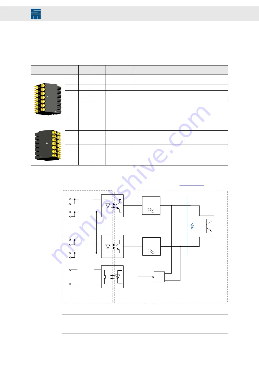
Safety circuit and restart lock (STO)
2 × 7-pole PCB connector, suitable for mating connector DFMC 0,5/ 7-ST-2,54
(Phoenix Contact)
Mating con-
nector X70
Pin
Pin
I/O
Name
Meaning
A1
B1
O
VCC24_STO
(1)
24 V
DC
auxiliary voltage, when STO is not required
Not suitable for OSSD supply!
A2
B2
I/O
GND
GND reference point for VCC24_STO
A3
–
O
X_SAFE_OK1
SAFE OK feedback, potential-free (see B3)
–
B3
O
X_SAFE_OK2
SAFE OK feedback, reference point for A3; potential-free
A4
B4
I
X_SAFE_0V
Reference point for X_SAFE_A/B
(When STO is not required: bridge A4 or A6 either with A2
or with B2.)
A5
B5
I
X_SAFE_B
STO input B
(When STO is not required: bridge A5 either with A1 or with
B1.)
A6
B6
I
X_SAFE_0V
Reference point for X_SAFE_A/B
(When STO is not required: bridge A4 or A6 either with A2
or with B2.)
Side A
Side B
A7
B7
I
X_SAFE_A
STO input A
(When STO is not required: bridge A7 either with A1 or with
B1.)
(1)
The 24 V output is not suited to supply external safety circuits because an external voltage source is
necessary to comply with the applicable standards. When the safety function (STO) is not required, this
voltage is used only to bridge the inputs X_SAFE_A and X_SAFE_B with the output VCC24_STO. In this
case, you must also bridge one of the contacts X_SAFE_0V with GND, see
OSSD
filter
OSSD
filter
X_SAFE_A
X_SAFE_B
X_SAFE_OK1
X_SAFE_OK2
Bridge
6x
SELV
PELV
≥1
X_SAFE_0V
X_SAFE_0V
A7
B7
A4
A5
B5
A6
B4
B6
A3
B3
Fig. 68: Safety circuit control
Note
You can use the identical signals of side A or B to forward the STO function to the next
drive.
83
Drive System SD4S - Hardware Description
Connectors


