background image

SR882 operation manual 

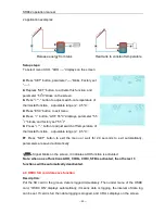
~ 30 ~


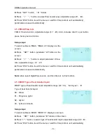
Setup steps: 

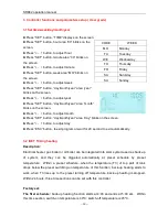
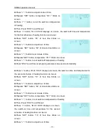
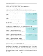
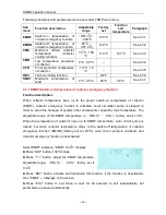
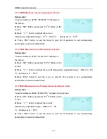
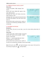
To  access  main  menu  TEMP,  then  select  submenu  CMX  “CMX  110

o

C”  displays  on  the 

screen. 

►Press “SET” button, parameter “110

” blinks. 

►Press  “+”“-”  button,  to  adjust  the  collector  protection 

temperature,  adjustable  range  (70

℃~

190

℃)

,  factory 

set is 110


►Repress  “SET”  button,  activate  and  deactivate  this 

function, if deactivate the function, “CMX - - -” displays on screen. 

►Press  “ESC”  button  to  exit  the  menu  or  wait  for  20  seconds  to  exit  automatically, 

parameters are saved automatically. 

CMX signal displays on screen, it indicates that this function is activated. 

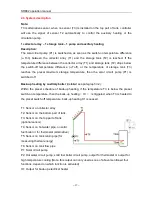
4.3.4 CMN low temperature protection of collector 

Description:   

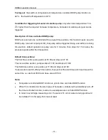
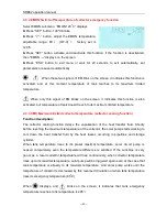
When the temperature of collector is below preset CMN temperatures, solar circuit pump is 

locked,  even  when  the  temperature  difference  between  collector  and  tank  exceeds  the 

switch-

on  temperature  difference,  solar  pump  doesn’t  work  yet.  When  temperature  of 

collector is 3

o

C higher that the preset CMN temperature, solar circuit pump is unlocked for 

operating, controller exits this program. 


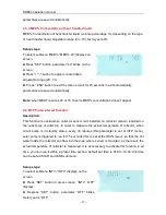
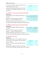
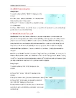
Setup steps

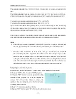
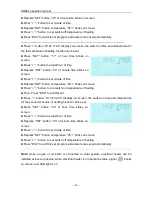
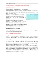
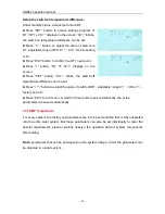
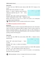
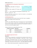
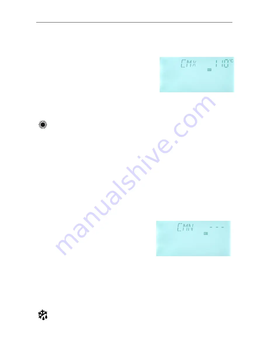
To  access  main  menu  TEMP,  then  select  submenu  CMN,  “CMN-----”  displays  on  screen, 

default set is off. 


►Press  “SET”  button,  default  off  signal  “-  -  -”  blinks 

on screen. 

►Repress  “SET”  button,  to  activate  and  deactivate 

this function   

►Press “+”“-” button, to adjust the low protection temperature of collector CMN, adjustable 

range (00

℃~

90

), after activate the function, factory set is 10


►  Press  “ESC”  button  to  exit  the  menu  or  wait  for  20  seconds  to  exit  automatically, 

parameters are saved automatically. 


CMN signal displays on screen, it indicates that this function is in activated.


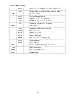
Summary of Contents for SR882

Page 1: ...Manual of Solar Pump Station SR882 for Split Pressurized Solar Hot water System 2011 07 07 ...

Page 2: ... and filling the solar system 7 3 2 Flow check 8 3 3 Airstopp 8 3 4 Electrical connection 9 3 5 Flushing and filling unit Spar part A06 10 Manual of integrated controller of solar station 11 1 Safety information 11 1 1 Description of symbols 11 2 Overview 11 2 1 Introduction of controller 11 2 2 Technical data 12 2 3 Terminal connection 13 2 4 Menu Structure 14 2 5 Menu description 15 2 6 System d...

Page 3: ...mal energy measuring 34 4 5 1 FTYPE Flow counter type option 35 4 5 2 FMAX Flow rate 36 4 5 3 MEDT Type of heat transfer liquid 36 4 5 4 MED Concentration of heat transfer liquid 37 4 6 INTV Pump interval function 37 4 6 1 ISTAR Turn on time for pump interval running function 38 4 6 2 IEND Turn off time for pump interval running function 38 4 6 3 ISTP Pump interval time 38 4 6 4 IRUN Pump running ...

Page 4: ...ory set 47 4 13 PASS Password set 47 5 Operation button function 49 5 1 Holiday function 49 5 2 Manual heating 49 5 3 Temperature check 50 6 Protection function 51 6 1 Memory protection 51 6 2 Screen protection 51 6 3 Circuit pump protection 51 7 Trouble shooting 51 7 1 Trouble protection 51 7 2 Trouble checking 52 8 Quality Guarantee 54 9 Accessories 55 ...

Page 5: ...tting for transferring heat from collector to storage It contains important fittings and safety devices for the operation of a solar thermal system Ball valves on flow and return in combination with check valves to prevent gravity circulation Airstopp for manual or automatic bleeding of the solar thermal system Flow rate check for displaying the flow rate Manometer for displaying the system pressu...

Page 6: ...for installation in the attic It is imperative that you make sure the PTFE sealing elements of the solar pump station do not come into contact with substances containing mineral oil Mineral oil products cause lasting damage to the material whereby its sealant properties are lost If necessary ask the manufacturer whether the solar fluid fats or installation aids contain mineral oils We don t assume...

Page 7: ...Fitting brass Seals PTFE Insulation EPP λ 0 041W m K 1 6 Technical Data Max permitted pressure 6bar Max permitted operating temperature 120o C Digital flow rate 0 1 20 L Min Mechanical flow rate 2 8 L Min 2 Mounting pump station Determine the mounting site of the station Take the station out of packing Remove the front half of the insulation Hold the enclosed wall mounting bracket against the wall...

Page 8: ...ne Attention Risk of frost Solar thermal system cannot be completely emptied after flushing There is a danger of frost damage if water is used for flushing Only use solar fluid to flush and fill the solar thermal system Use water propylene glycol mixture as solar fluid Maximum 50 propylene glycol 3 1 Flushing and filling the solar system Flushing and filling unit is the optional component it can b...

Page 9: ...anometer Close the filling ball valve 1 of the flushing and filling unit and then close the filling pump Check the manometer to see whether the system pressure reduces and eliminate leaks where necessary Reconnect the expansion vessel to the solar thermal system 3 2 Flow check The flow counter is used for measurement and display of flow rate 1 20L M in order to guarantee the flawless function of t...

Page 10: ...n Warning high temperature scald During air releasing temperature of released air and liquid maybe over 100o C 3 4 Electrical connection Warning disconnect the controller from power supply before opening the housing The controller is already integrated in the station and ready to plug in Pump pipe sensor and digital counter are already pre connected with controller at factory But for connecting ot...

Page 11: ...eration manual 10 3 5 Flushing and filling unit Spar part A06 Flushing and filling unit is a optional accessory part of system it is not included in the standard scope of delivery please prepare separately A06 ...

Page 12: ...on and the resulting damage we do not take responsibility 1 1 Description of symbols Safety instruction The safety instruction in the manual is marked with a warning triangle They indicate measures which can lead to personal injury and safety risks Operation steps small triangle is used to indicate operation step Notes Contains important information about operation or function 2 Overview 2 1 Intro...

Page 13: ... of temperature measuring 2o C Range of collector temperature measuring 10 200o C Range of tank or pipe temperature measuring 0 110o C Inputs 1 x Pt1000 sensor 500 o C for collector silicon cable 280 o C 5 x NTC10K B3950 sensor 135o C for tank PVC cable 105o C 1 x RS485 remote control connection Outputs 1 PWM outputs 200W 1 relays outputs each available power 300W 1 output for electrical booster a...

Page 14: ...ot necessary to distinguish the positive and negative polarity of the sensor connection 2 Only original factory enclosed NTC10K B 3950 temperature sensors are approved for use with tank and pipe it is equipped with 1 5meter PVC cable and they are temperature resistant up to 105 o C not necessary to distinguish the positive and negative polarity of the sensor connection 3 All sensor cables carry lo...

Page 15: ...und line terminal Output P1 For solar circuit pump also suitable for RMP control semiconductor relay max switching current 1A Output P2 Electromagnetic relay its max switching current 3 5A Output H1 For back up electrical heater electromagnetic relay max switching current 10A 2 4 Menu Structure Submenu Through submenu user can set the parameter as desired value please check it carefully ...

Page 16: ...eters for pump speed adjust nMIN Speed controlling of circulation pump RPM pump controlling DTS Standard temperature difference for circulation pump speed adjust RIS Increase scale circulation pump speed adjusting parameter set OHQM Thermal energy measuring FTYPE Select type of flow counter FMAX Flow rate MEDT Type of heat transfer liquid MED Concentration of heat transfer liquid INTV Pump interva...

Page 17: ...oling function AHO Switch on temperature for thermostat AHF Switch on temperature for thermostat OSDC SD card function LOGI Data saving interval time in minute NOCRD FAT16 FAT32 No card in groove EMS memory 2G EMS memory 2G RTIME Rest days for data saving in day FSYS LOGG System file error Log possible UNIT Celsius and Fahrenheit temperature switch HDN Manual controlling REST Recovery to factory s...

Page 18: ...he solar circuit pump P1 is switched off Back up heating by auxiliary boiler detailed see paragraph 3 2 Within the preset schedule of back up heating if the temperature T3 is below the preset switch on temperature then the back up heating H1 is triggered when T3 is heated to the preset switch off temperature back up heating H1 is ceased T1 Sensor on collector array T2 Sensor on the bottom part of ...

Page 19: ...s ESC button to exit program or wait for 20 second to exit automatically 3 2 tHET Timing heating Description Electrical heater gas boiler or oil boiler can be integrated into solar system used as back up of system and they can be triggered automatically at preset schedule by preset temperature Within a preset schedule when the temperature T3 of top part of tank drops below the preset switching on ...

Page 20: ... sensor controller will take the signal of T2 sensor in bottom of tank automatically to control this function The time in this controlled is 24 hours mode when you set schedule the switch off time of heating should be larger than the switch on time For example if you set the switch on time of heating is at 17 00 but switch off time of heating is 6 00 then this setting doesn t take effect that mean...

Page 21: ...n to set switch off temperature of heating Press ESC to exit this set program parameters are saved automatically Press button tH 2o 10 00 displays on screen the switch on time and temperature for the second schedule of heating function can be set Press SET button 10 of hour time blinks on screen Press button to adjust hour of time Repress SET button 00 of minute time blinks on screen Press button ...

Page 22: ... button temperature 50 blinks on screen Press button to set switch on temperature of heating Then Press ESC to exit this set Press button tH 3F 22 00 displays on screen the switch on time and temperature for the second schedule of heating function can be set Press SET button 22 of hour time blinks on screen Press button to adjust hour of time Repress SET button 00 of minute time blinks on screen P...

Page 23: ...OFF Press SET button parameter OFF blinks on the screen Repress SET button to activate this function CIRC ON appears on the screen Press ESC to exit this submenu or wait for 20 seconds to exit automatically the parameter valves are saved automatically Press button tCYC appears on the screen Press SET button to access tCYC menu Press SET button access tCYC three schedules function tC 1o 05 00 appea...

Page 24: ...ss ESC to exit this set program parameters are saved automatically Press button tC 2o 11 00 appears now can set the second turn on time Press SET button again 11 of hour time blinks on screen Press button to adjust hour of time Repress SET button 00 of minute time blinks on screen Press button to adjust minute of time Repress SET button 03 Min of pump running time blinks on screen Press button to ...

Page 25: ...rd turn off time Press SET button again 22 of hour time blinks on screen Press button to adjust hour of time Repress SET button 00 of minute time blinks on screen Press button to adjust minute of time Repress SET button 15 Min of pump stop time blinks on screen Press button to adjust pump stop time Press ESC to exit this set program parameters are saved automatically Description of temperature con...

Page 26: ...es then stops for 15 minutes the process repeats within the time section Default time sections The first time section pump works at 05 00 and stops at 07 00 The second time section pump works at 11 00 and stops at 13 00 The third time section pump works at 17 00 and stops at 22 00 If user wants to switch off any time section then just set the start time and close time with a same time i e starts a...

Page 27: ... exit main menu Note factory set password is 0000 if don t set new password then continuously press SET button four times to access main menu 4 2 DT Temperature difference function Description Solar circuit pump P1 is triggered by the temperature difference function so long as the temperature difference between collector and tank reaches the switch on DT solar circuit pump is triggered For example...

Page 28: ...witch off temperature difference can be set Press button to adjust the value of switch off DT adjustable range 0 ON 2 factory set is 4 Press ESC to exit menu or wait for 20 seconds to exit automatically the setup parameters are saved automatically 4 3 TEMP Temperature For every system the factory set parameters are in the best condition that is fully integrated into the entire solar system But the...

Page 29: ...on When collector temperature rises up to the preset switch on temperature of collector EMOF collector emergency function is activated solar circulation pump is stopped in order to avoid the damage of system other components caused by high temperature The adjustable range of this EMOF temperature is ON 3 200 factory set is 130 When the temperature of collector rises up to EMOF temperature solar ci...

Page 30: ...ximum limited collector temperature collector cooling function Function description The collector cooling function delays the vaporization of the heat transfer fluid Shortly before reaching the maximum temperature of the collector the solar pump starts working to cool down the heat transfer fluid by the heat losses occurring in pipelines and storage cylinder When tank temperature rises to its pres...

Page 31: ...emperatures solar circuit pump is locked even when the temperature difference between collector and tank exceeds the switch on temperature difference solar pump doesn t work yet When temperature of collector is 3o C higher that the preset CMN temperature solar circuit pump is unlocked for operating controller exits this program Setup steps To access main menu TEMP then select submenu CMN CMN displ...

Page 32: ...unction Press button to adjust the temperature of frost protection function adjustable range is 10 10 after function activated default set is 4 Press ESC button to exit the menu or wait for 20 seconds to exit automatically parameters are saved automatically CFR signal displays on screen it indicates that this function is activated Note this function is only available in special solar system which ...

Page 33: ...op part of tank is higher than the maximum temperature of tank when T3 is higher than preset SMX temperature solar pump is ceased even at the case that DT caters condition When tank temperature drops and is 2o C below the SMX solar pump restarts when DT caters condition Setup steps To access main menu TEMP then select submenu SMX SMX 60o C displays on screen Press SET button parameter 60 blinks Pr...

Page 34: ...on to adjust pump speed adjustable range 30 100 factory set is 100 Press ESC button to exit the menu or wait for 20 seconds to exit automatically parameters are saved automatically 4 4 1 DTS Standard temperature difference for circulation pump 1 speed adjusting Description The preset default minimum pump speed in this controller is 30 When the switch on temperature difference TON reaches solar pum...

Page 35: ...SC button to exit the menu or wait for 20 seconds to exit automatically parameters are saved automatically 4 5 OHQM Thermal energy measuring Description Controller has function for measuring the thermal energy it can measure the energy which is transferred from collector to tank For the sake of measuring the temperature on flow and return pipe should be checked and an extra flow meter should be in...

Page 36: ...cleared and daily thermal energy is reset to 00 Press button select to check accumulative thermal energy KWH XX or MWH XX SET displays on the screen Press SET button for 3 seconds buzzer makes 3 times du the sum thermal energy is cleared and accumulative thermal energy is reset to 00 Press button select the operation time of pump hP XX SET displays on the screen Press SET button for 3 seconds buzz...

Page 37: ...ust parameter of flow rate adjustable range 0 1 20 Press ESC button to exit the menu or wait for 20 seconds to exit automatically parameters are saved automatically Note when select digital flow counter and then there is no this function 4 5 3 MEDT Type of heat transfer liquid MEDT type of heat transfer liquid adjustable range 00 03 factory set 01 Type of heat transfer liquid 00 Water 01 Propylene...

Page 38: ...ption This function is useful when collector sensor isn t installed on collector sensor installed on the outlet pipe of collector In order to measure the actual temperature of collector when circuit pump is in standby status every 30 minutes this parameter is set at ISTP menu solar pump is triggered to run for 15 seconds this is set at the IRUN menu so that the hot water inside the collector can f...

Page 39: ...omatically parameters are saved automatically 4 6 2 IEND Turn off time for pump interval running function Setup steps To select submenu IEND IEND 18 00 displays on the screen Press SET button parameter 18 00 blinks Press button to adjust turn off time Press ESC button to exit the menu or wait for 20 seconds to exit automatically parameters are saved automatically 4 6 3 ISTP Pump interval time Setu...

Page 40: ...T3 rises up to the preset turn off temperature of solid fuel boiler SFOF or when temperature of the solid fuel boiler T4 exceeds its MIN3 and MAX3 that is T4 MAX3 or T4 MIN3 then solid fuel boiler is stopped Note the preset MIN3 should be at least 1o C higher than the preset SFOF for example set SFON is 50o C SFOF is 55o C then MIN3 should be at least 1o C higher than SFON namely it is 56o C Then ...

Page 41: ...5o C displays on the screen Press SET button parameter 55 o C blinks on the screen Press button to adjust the turn off temperature adjustable range ON 2 o C 80 o C factory set is 55 o C Press ESC button to exit the menu or wait for 20 seconds to exit automatically parameters are saved automatically 4 7 3 MAX3 Maximum turn off temperature of solid fuel boiler Setup steps To select submenu MAX3 MAX3...

Page 42: ...tic valve When all inputs and outputs have been occupied function you selected may not be available for activating In such case you can t see the submenu options Following submenu can be accessed through menu FUN Submenu under FUN Description Paragraph DVWG Anti legionnaires function 4 8 1 COOL Tank cooling function 4 8 2 AHO Auto thermostat function 4 8 3 4 8 1 DVWG Anti legionnaires function Des...

Page 43: ...emperature so extra energy in tank will be transferred to other devices to achieve this function it is necessary to add a electromagnetic valve or a circuit pump P2 its temperature is monitored by T3 For example The set point of tank high temperature cooling function is 70o C then when tank temperature T2 rises up to 71 o C tank cooling function is activated electromagnetic valve or circuit pump a...

Page 44: ... is always same it is independent of the solar system s operation when tank temperature is below the switch on temperature ATO of this function the function controls to trigger back up heating device When tank is overheated this function will transfer heat energy from tank to other place and ensure tank temperature is constant For this function it is necessary to install an extra electromagnetic v...

Page 45: ... Press button to adjust switch off temperature of thermostat function adjustable range 2 95 o C Press SET button to exit the menu or wait for 20 seconds to exit automatically parameters are saved automatically Signal blinks on the screen it indicates AHO function is activated Note when one of functions AHO COOL CIRC SFB is activated then the rest 3 functions will be automatically deactivated 4 9 O...

Page 46: ...xit automatically parameters are saved automatically 4 9 2 LOGI Data save intervals Description By this function SD card can save data in every 60 seconds factory default time 60 seconds Setup steps To select menu LOGI LOGI 60 displays on the screen Press SET button to access program LOGI 60 appears and 60 blinks Press button to adjust data save interval adjustable range 01 1200 seconds Press ESC ...

Page 47: ...oller first time or when debugging this controller output of this controller P1 P2 H1 can be triggered manually with On OFF control Setup steps To access main menu HND Press SET button HND1 off displays on the screen P1 output manually set Repress SET button HND1 on displays on the screen P1 output is switched on Repress SET again HND1 off displays P1 Short message Code Description FSYS File syste...

Page 48: ...in HND3 off displays H1 output is switched off Press ESC to exit H1 set program Note when manual mode is activated signal displays on the screen after 15 minutes all outputs are switched off controller exits manual mode automatically 4 12 REST Recovery to factory set Setup steps To access main menu REST Press SET button YES displays on the screen Hold down SET button buzzer makes du 3 times then r...

Page 49: ...ssword Press SET button PWDG 0000 displays on the screen ask for reentering the new password doing like above to reenter the new password PWOK displays on the screen to indicate reentering password successfully Press ESC button to exit set program or wait for 20 seconds to exit automatically Warning If the password is forgot it is not possible to recover but you can recover the password to factory...

Page 50: ...ated when the temperature in lower section of storage tank falls down to 35o C Activate deactivate this function Press Holiday button for a long time until the signal of holiday function displays on the screen and then holiday function is activated Repress Holiday button signal disappears holiday function is deactivated Note This function is only activated when you are not at home for long time wh...

Page 51: ...ed automatically if customer wants to heat again you need redo according to above steps 5 3 Temperature check Under standby status Press button can check the value of temperature sensors T1 T6 flow rate pump speed n accumulative operation time of circuit pump hp daily thermal energy DKWH accumulative thermal energy KWH or MWH Time and Date When checking temperature T1 T6 will display one by one co...

Page 52: ...d in solar system when controller monitors that there is no flow in the pipe circuit pump P1 will be not triggered anymore P1 displays on the screen Switch off the power supply of controller to exit the protection reset the P1 7 Trouble shooting 7 1 Trouble protection a When there is a break or short circuit between the connection of temperature sensors controller switches off the corresponding fu...

Page 53: ...ring function is activated T5sensor not connected on controller Connect T5 or close QHQM function 7 2 Trouble checking The controller is quality product conceived for years of continuous trouble free operation If a problem occurs the cause of the problem very often lies not in the controller but in the peripheral components The following description of some well known problems should help the inst...

Page 54: ...circuit or open circuit in a temperature sensor On the controller check the current values of all connected temperature sensors replace all defective sensors and or cabling The solar pumps operated despite the fact that the switch on conditions are not satisfied The pump symbol on the display blinks Holiday function or Frost protection function or tank re cooling function is activated No problem i...

Page 55: ...n will not lead to failure When a user takes incorrect handling way incorrect installation improper or crud handling wrong connection of sensor in system and incorrect operation the quality responsibility is invalid for them The warrantee expires within 24 months after the date of purchasing the controller 0 10 20 30 40 50 60 70 80 90 100 110 120 Ω 1000 1039 1077 1116 1155 1194 1232 1270 1309 1347...

Page 56: ... 50 A05 stainless steel thermowell Parameter 1 2 OT Ф8 200 SR802 unit for high power electrical heater Dimension 100mmx100mmx65mm Power supply AC180V 264V 50 60Hz Suitable power 4000W Available ambient temperature 10 50o C Waterproof grade IP43 SR802 connection diagram Note switch off power and perform by profession installer ...

Reviews: