8
SE130/250T IP Ignition Protected thruster assembly
versjon1.3 - 2015
8
SP75Ti / SP95Ti ignition protected thruster assembly
1.2 - 2005
1.
Remove the 4 bolts in the motorbracket.
2.
Mount the lower part of the flexible coupling and tighten the set screws (two for SP75Ti IP, one for SP95TI IP). Insert the "rubber/
plastic ring" in this lower part.
3.
Place the motor gently on the motorbracket. Be careful, the motor is heavy! Ensure that the "rubber/plastic ring" goes into position.
Ensure that you are placing the motor so that the cable terminals on it are available for electric installation later.
4.
Fasten the motor to the bracket with the 4 bolts and tigthen them.
5.
If you are installing a SP95Ti IP in an angle of more than 45
o
off a vertical position, the electromotor needs a separate/additional
support. See illustration in the measurements drawings.
6.
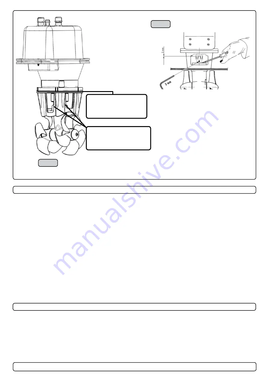
Lift the lower part of the flexible coupling together with the rubber/plastic ring into the upper flexible coupling. The rubber/plastic ring
must be in its correct position in the upper part, fully inserted but not com-pressed against it (SP75Ti IP:17 mm - SP95Ti IP: 2mm).
Secure the lower part of the flexible coupling in its new position by tightening the set-screws (two for SP75Ti IP, one for SP95TI IP).
NB !
Paint the gearhouse and propeller with antifouling for propellers to prevent growth of barnacles or similar which would reduce the
performance dramatically. Do not paint the propeller shaft, the zincanodes or the end face of the gearhouse.
Fitting the electromotor IP assembly
SP95Ti IP
SP75Ti IP
Bolt tightening force (4x):
SP75Ti: 33 Nm (24 lb/ft)
SP95Ti: 33 Nm (24 lb/ft)
Bolt tightening force (2x):
SP75Ti: 17 Nm (12,4 lb/ft)
SP795Ti: 17 Nm (12,4 lb/ft)
Final gearleg assembly
1. Remove the 4 bolts in the motorbracket.
2. Mount the lower part of the flexible coupling and thighten the set screw. Insert the red "plastic ring" in the lower part
3. Place the motor gently onto the driveshaft and the motor bracket. Be careful, the motor is very heavy! Ensure that the "plastic
ring" goes into position. Ensure that you are placing the motor so that the cable terminals are available for electric installation later.
4. Fasten the motor loosely to the bracket with the provided bolts.
5. Tighten the 4 bolts holding the motor to the motorbracket.
6. Lift the lower part of the flexible coupling together with the plactic ring into the upper part of the fleixible coupling. The plastic ring
must be in its correct position in the upper part, fully inserted, but not compressed against it (2mm). Secure the lower part of the
coupling in its new position by tightening the set-screw.
7. Check the system by turning the propeller, it will be a little hard to turn (because of the gear reduction and the motor), but you
should be able to turn it by hand.
8. If you are installing the thruster in an angle of more than 45
o
off a vertical position, the electromotor assembly needs a seperate/
additional support. See illustration on previous page
.
Paint the gearhouse and propeller with antifouling for pro-pellers to prevent growth of barnacles or similar which would reduce the
performance dramatically. Do not paint the propeller shaft, the zincanodes or the end face of the gearhouse.
Fitting the electromotor IP assembly
Final gearleg assembly
Fig. 2
Bolt tightening force (4x):
33 Nm (24 lb/ft)
Bolt tightening force (2x):
33 Nm (24,4 lb/ft)
Fig. 1


