✓
The color of the marking rectangle changes to red.
3.
Re-click the marking rectangle.
✓
SOPAS removes the marker square and instead connects the two nearest marker
squares with a new line.
Rotating the field pair and device around the central axis
b
In order to align the position of the field pair in SOPAS to the conditions on site
from the user´s perspective, enter and confirm the desired angle of rotation in the
0.0° input. A negative “-” sign sets the turning direction to the right.
Setting up the contour as reference field
In each field set, any field can be selected as a contour as reference field.
The contour as reference field is used to monitor contours. This can be used to check
whether the background is still recognized correctly. If this is no longer the case,
possible reasons are that the device is covered or rotated.
The same evaluation strategy is used for all contour as reference fields (evaluation time
and blanking size).
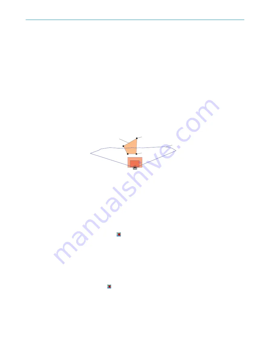
Contour as reference field
1
Field start point
4
Field end point
2
Scan line
3
1
Contour as Reference field
2
End point of contour
3
Scanning line
4
Start point of contour
1.
Select the required field in the field set.
2.
Select the
contour as reference field
check mark under
Field selection
.
3.
Delete the two field positions closest to the device.
4.
Mark the two remaining field positions and shift them outside of the required
reference contour area.
5.
The button can switch to the configuration for the contour as reference field
start points.
The field starting points must lie between the scan line and the device so that the
scan line passes between the start and end points of the contour as reference
field.
6.
Depending on the required shape of the reference contour field, create additional
field points between the device and the reference contour field. The distance
between the start and end points of the contour as reference field should be
approximately 20 cm.
The button can be used to switch between the start and end points of the contour
as reference field for editing purposes. The active points are highlighted in light green
while the deactivated points are dark green.
7.3
ROS driver
Suitable drivers for integrating the device into the ROS (Robot Operating System) are
available for download on the product page:
OPERATION
7
8024851//2021-07-21 | SICK
O P E R A T I N G I N S T R U C T I O N S | TiM3xx
47
Subject to change without notice


