8026880
QUICKSTART TDC-EX10XX
• 2022/03/15 • Subject to change without notice • SICK AG • Waldkirch • Germany •
www.sick.com
TELEMATIC DATA COLLECTOR TDC-EX10XX | SICK
2
TDC-E device comes without installed SIM card. If there is a
need to install (or replace) the SIM card, follow the lower
instructions.
CAUTION
•
Always disconnect the device from power supply before
replacing/installing the SIM card.
•
In all cases, take measures to protect against
electrostatic discharge.
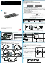
Proceed as follows to replace/install the SIM card:
1.
Make sure that the device is switched off.
2.
Unscrew and remove the plastic cover on the bottom side
of the device.
3.
Push the plastic cover of the SIM card holder to the side.
Orientation is marked on holder with arrow.
4.
Lift the SIM plastic holder and replace/install the SIM card
facing chip side down.
5.
Return the SIM plastic cover and lock it.
6.
Return the enclosure plastic cover to the bottom side of the
device and secure it with screws.
7. Set up APN in TDC-E Device Manager (refer to operating
instructions)
Input voltage
9 V – 36 V DC
Max current
consumption
2A Max current consumption
Average current
consumption
100 mA @ 24 V (without external load)
Protection
Overcurrent, overvoltage and ESD protection (4kV IEC
61000-4-2)
Fuse
4A (internal)
Operating
temperature
-20 °C to +70°C
Storage temperature
-40 °C to +85 °C
Case material
PA6
Flammability class
UL 94 V-0
Dimensions without
antennas (W×H×L)
162.0 x 31.7 x 101.0 mm
6.38 x 1.25 x 3.98 inch
Protection type
IP20 according to DIN EN 60529
Weight without
accessories
230g
GC (Global frequency
coverage model)
1)
LTE-FDD:
700/800/850/900/1700/1800/1900/2100/2600
LTE-TDD: 1900/2300/2500/2600MHz
UMTS: 850/900//1700/1900/2100MHz
GSM
2)
: 850/900/1800/1900 MHz
Data transfer speed up to 150 Mbps (DL)/50Mbps
(UL) for LTE FDD
•
SIM
3)
User replaceable, standard SIM card size (2FF)
•
Antenna
No cable allowed between antenna and connector
•
SMS
Text and PDU mode
GPS Receiver type
72-channel u-blox M8
GPS, GLONASS, BeiDou, Galileo
Satellite-based augmentation systems L1 C/A: WAAS,
EGNOS, MSAS, GAGAN
•
Sensitivity
-148dBm (acquisition)
-164dBm (tracking)
•
Time to
first fix
Hot start: 1 s
Warm start: 3 s
Cold start: 32 s
•
Max
update
rate
10 Hz
•
Antenna
Internal and external MCX option
Antenna cable is limited to maximum permissible
length of <3m
WPAN
Dual-Mode:
IEEE 802.15.1
WLAN
IEEE 802.11 b/g/n
1)
Full 4G performance cannot be guaranteed on operating
temperature over 60°C
2)
Not available for end user
3)
TDC-E device delivered without SIM card
TDC-E
Description
6 x AIN (Analog input)
1)
•Analog measurement of voltage (0 – 36 V) with
accuracy of ±0.2% (+30mV) or current (0 – 32
mA), with accuracy of ±1% (+0.1mA)
•Virtual digital input capability (fully configurable
high and low voltage levels)
•Input resistance 27.5 kΩ typical for voltage
mode, 100 Ω typical for current mode
6 x DIO (Digital
input/output)
1)
•Digital input (high level > 3 V) or digital output
(500 mA current capability, 1000 mA is maximal
load on all outputs combined, high-side switch
outputting voltage from device power input),
software configurable, overcurrent protected
•Impulse/frequency measurement (high level >
3V)
•Input resistance: 22 kΩ typical for digital input
2x DOUT (Additional
digital output)
•Additional digital output on LP_A/B pins
•Max current of 300 mA
2 x DIN (Additional
digital input)
•Additional digital input on CQ_A/B pins
2xEthernet
•2 x RJ45, 10/100/1000 Mbit/s
RS-485/RS-422
1)
•Fully compliant with ANSI TIA/EIA 485-A
•ESD protection (± 6kV IEC 1000-4-2)
•Selectable baud rate up to 576 kbps
SSI
1)
•SSI master interface
•Available if RS-485/RS-422 disabled in
software
1)
•Minimum clock rate is restricted to 300 kHz
while maximum is 1 MHz
RS-232
•True RS-232 (EIA/TIA-232/V.28) level Receive
and Transmit data lines
•ESD protection ±8 kV (contact discharge)
according to IEC 61000-4-2
•Selectable baud rate up to 250 kbps
•Cable is limited to maximum permissible length
of <3m.
2xCAN bus
•ISO 11898-2 and ISO 11898-5 compliant
•ESD protection ±8 kV (contact discharge)
according to IEC 61000-4-2
•Selectable baud rate up to 1 Mbps
1-Wire
•1-Wire interface
•28 V overvoltage protection
•ESD protection ±4 kV (contact discharge)
according to IEC 61000-4-2
•Cable is limited to maximum permissible length
of <3m.
USB
•USB 2.0 host
•Allowed to be used only for storage, with no
cable allowed between connector and USB flash
drive.
•ESD protection ±8 kV (contact discharge)
according to IEC 61000-4-2
1)
software configurable
TDC -E
Description
Accelerometer
•3 axis
•Full scale range: ±2g/±4g/±8g
•Resolution: up to 0.244 mg
•Report rate: 1.56 Hz to 400 Hz
Magnetometer
•3 axis
•Full scale range: ±12000 mGa
•Resolution: up to 1 mGa
•Refresh rate: up to 100 Hz
Thermometer
•Resolution: ±0.5°C
•Accuracy: ±0.5 °C from −20 °C to +100 °C
1)
only for diagnostic purpose
TDC-E-front side
TDC-E-back side
1.LED indicator
6.MCX connector-GPS antenna
2.TDC-E PWR+AIN/DIO
connector (14 pin connector)
(only available in TDC-E200XX
model)
3.TDC-E COMM connector
(20 pin connector)
7.SMA connector-LTE antenna
(not available in models without LTE)
4.RJ45 GbE port0 (Eth0)
8.SMA connector-WLAN+WPAN
antenna
5.RJ45 GbE port1 (Eth1)
9. USB 2.0 connector
Figure 2: TDC-E device overview and interfaces
Port
Default IP address
GbE port0 (Eth0)
192.168.0.100
GbE port1 (Eth1)
by DHCP
All ports/connectors are described from side of device.
TDC-E PWR+AIN/DIO connector terminals:
Group
Pin
Pin
name
Description
PWR
14
VIN
Power supply for device. Power supply
range 9V – 36V DC
7
GND
Ground pin for power supply
DIO
13
DIO_A
Digital input/output - Channel A
6
DIO_B
Digital input/output - Channel B
12
DIO_C
Digital input/output - Channel C
5
DIO_D
Digital input/output - Channel D
11
DIO_E
Digital input/output - Channel E
4
DIO_F
Digital input/output - Channel F
AIN
10
AIN_A
Analog input – Channel A
3
AIN_B
Analog input – Channel B
9
AIN_C
Analog input – Channel C
2
AIN_D
Analog input – Channel D
8
AIN_E
Analog input – Channel E
1
AIN_F
Analog input – Channel F
TDC-E COMM connector terminals:
Group
Pin
Pin
name
Description
Additional
DIO
20
LP_A
LP_A pin is used as digital output
10
CQ_A
CQ_A pin is digital input
Additional
DIO
19
LP_B
LP_B pin is used as digital output
9
CQ_B
CQ_B pin is digital input
GND
18
GND
GND pin
8
GND
GND pin
+5V
DO
17
5V
5V digital output
1-WIRE
7
1W
Data pin for 1-WIRE
RS-232
16
TX
Data transmit output pin for RS-
232 protocol
6
RX
Data receive input pin for RS-232
protocol
15
CTS
CTS-Clear to send output pin for
RS-232 protocol
5
RTS
RTS-Request to send input pin for
RS-232 protocol
RS-485/
RS-422/
SSI
1)
14
Y/CLK+
Data pin for RS-485/RS-422/SSI
4
Z/CLK-
Data pin for RS-485/RS-422/SSI
13
A/DATA+
Data pin for RS-485/RS-422/SSI
3
B/DATA-
Data pin for RS-485/RS-422/SSI
CAN A
12
CANH_A
CAN high data pin – Channel A
2
CANL_A
CAN low data pin – Channel A
CAN B
11
CANH_B
CAN high data pin – Channel B
1
CANL_B
CAN low data pin – Channel B
1)
software configurable/RS-422 available in API
RS-485/RS-422 Pinout
Half duplex mode
: Transceiver operates in
transmit and receive
modes using
Y
and
Z
pins.
Full-duplex mode
: Transceiver operates in
receive mode
on
A
and
B
pins and
transmit
mode on
Y
and
Z
pins.
For further information refer to the operating instructions.
Replacing/installing the SIM card
Technical data
Interfaces
Embedded sensors
1)
Device overview and interfaces
Overview of ports/connectors pinout and design