3.3.2
Compatible sensor types
Table 1: Compatible sensor types
Sensor type
Examples
Flexi Loop safe series connection
Flexi Loop
3.3.3
Restart interlock
A restart interlock can be implemented with a reset pushbutton.
3.3.4
External device monitoring
Permanent external device monitoring can be implemented using external wiring.
3.3.5
Status indicators
LEDs
R
E
L
Y
PWR
OUT
13
23
I1
Y1
14
24
I2
Y2
A2
S1
33
A1
34
X1
PWR
OUT
13
23
I1
Y1
14
24
I2
Y2
A2
A1
S1
X1
LOOP1
1100696
R
E
L
Y
33
34
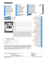
Figure 2: LEDs
The labeled positions are only partially assigned LEDs. The positions and their labeling
(except for the upper 2 lines) also show the pin assignment of the terminals on the front
connector.
Table 2: Safety relay indicators
Labeling
Color
Function
PWR
Green/Red
Voltage supply
OUT
Green
Enabling current paths
I1
Green
Safety capable input
I2
Green
Safety capable input
S1
Green
Reset pushbutton input, exter‐
nal device monitoring (EDM)
Y1
Green
Application diagnostic output
(NC)
Y2
Green
Application diagnostic output
(reset required)
Further topics
•
"Status indicator (LED)", page 26
3
PRODUCT DESCRIPTION
10
O P E R A T I N G I N S T R U C T I O N S | ReLy LOOP1
8024311/2021-07-30 | SICK
Subject to change without notice