•
It must be possible to electrically influence the control of the machine
•
The electrical control of the machine must meet the requirements of IEC 60204-1
•
When using a safety controller, different signal levels of both OSSDs must be
detected depending on applicable national regulations or required reliability of the
safety function. The maximum discrepancy time tolerated by the control must be
selected according to the application.
•
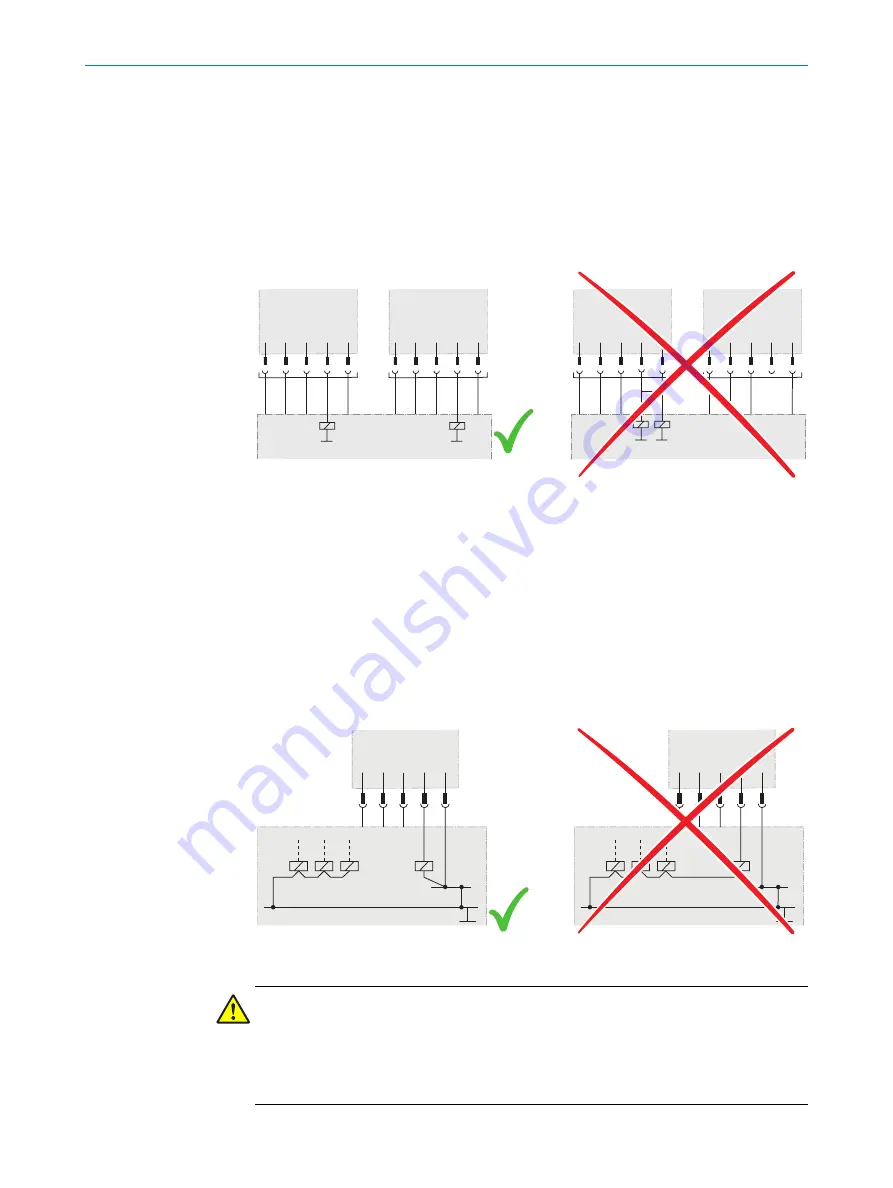
The OSSD1 and OSSD2 output signals must not be connected to each other
•
In the machine controller, the signals of both OSSDs must be processed sepa‐
rately
OSSD1
OSSD2
OSSD1
OSSD2
Figure 20: Dual-channel and isolated connection of OSSD1 and OSSD2
•
The machine must switch to the safe state at any time if at least one of the two
OSSDs switches to the OFF state
•
Prevent the formation of a potential difference between the load and the protec‐
tive device. If loads are connected to the OSSDs (switching outputs) that then also
switch if controlled with negative voltage (e.g., electro-mechanical contactor with‐
out reverse polarity protection diode), the 0 V connections of these loads and
those of the corresponding protective device must be connected individually and
directly to the same 0 V terminal strip. In the event of a fault, this is the only way to
ensure that there can be no potential difference between the 0 V connections of
the loads and those of the corresponding protective device.
O
S
SD
0 V
OSSD
0 V
Figure 21: No potential difference between load and protective device
DANGER
Hazard due to unexpected starting of the machine
A restart interlock must be implemented depending on applicable national regulations
or required reliability of the safety function.
b
Make sure that a restart interlock is implemented.
4
PROJECT PLANNING
30
O P E R A T I N G I N S T R U C T I O N S | miniTwin4
8012624/10OM/2018-08-09 | SICK
Subject to change without notice


