TE C H N I C A L I N F O R M A T I O N
HC8XHeat Control
InstallationOperationMaintenance
Page 1: ...TE C H NI CA L I NFO RMA T I ON HC8X Heat Control Installation Operation Maintenance ...
Page 2: ...rights reserved 8010043 Document Information Copyright Copyright 2013 SICK AG Printed in the Federal Republic of Germany Editor SICK AG Erwin Sick Str 1 79183 Waldkirch Germany Phone 49 7641 469 0 Fax 49 7641 469 1149 Part No 8010043 Release 1 1 Date 2013 01 ...
Page 3: ...Manufacturer SICK AG Erwin Sick Str 1 79183 Waldkirch Germany Phone 49 7641 469 0 Fax 49 7641 469 1149 EMail info pa sick de Cusotmer Servcie Your local representative will be glad to answer your questions and give you any support required You will find our local subsidiary or agency at www sick com ...
Page 4: ...ting the Temperature Sensors 23 3 5 Connecting the Optical Fibers 24 3 6 Connecting the Control Electronics Supply Voltage 25 3 6 1 Supply Voltage and Fuse Preselection Primary Side 25 3 6 2 Connecting the Supply Voltage 25 4 Configuration and Addressing 26 4 1 Preparations 26 4 2 Overview for Parameter Settings26 4 3 Parameter Setting with HC8XINIT EXE under MS DOS 26 4 3 1 HC8XINIT EXE DOS Optio...
Page 5: ...with an Odd Number of Channels 38 7 2 Configuring the Power Bars 39 8 Troubleshooting 41 8 1 Power Electronics Overload Protection 41 8 2 Primary Side Fuses of the Control Electronics 41 8 3 Secondary Side Fuses of the Control Electronics 41 8 4 Automatic Over Temperature Protection of Control Electronics 42 9 Disposal 43 9 1 Disposal after Final Shut Down 43 10 Technical Data Annex 44 10 1 Dimens...
Page 6: ... engineers Information depth This document contains all information required for mounting electrical installation and start up of the HC8X with the basic factory settings All these activities are explained step by step The configuration of the HC8X for the specific application usage is performed with the DOS 6 22 oriented HC8XINIT EXE utility program or with the Windows oriented SETHC8X EXE utilit...
Page 7: ...acteristics Explanation An explanation provides background knowledge on technical interdependencies Recommendation A recommendation is an aid to the optimum performance of an activity Tip A tip explains setting options for the SETHC8X EXE user interface Basic setting Marks a section in which the values of the basic factory setting are listed This symbol marks a section in which operating steps wit...
Page 8: ...mal operation of the control unit only appropriately trained and skilled per sonnel should be allowed to operate the control unit Unauthorized Adjustments and Servicing Only a SICK service engineer or a similarly trained and authorized person should be per mitted to perform service work or adjustments on the control unit Please observe the following safety recommendations Do not attempt to make in...
Page 9: ...ntrol unit may be connected to the mains only by authorized qualified personnel Only a SICK service engineer or similarly trained and authorized person should be per mitted to service or repair the control unit The control unit operates with high voltages Even with the power switched OFF high voltages can be present inside the control unit When the control unit is switched on the electrical connec...
Page 10: ... the control unit Shows visible damage or has been subjected to prolonged storage under unfavorable conditions e g humidity Has not been correctly handled during transport Damaged control unit Do not put a damaged control unit into operation Whenever it is likely that the control unit is no longer electrically safe for use place the control unit out of operation and secure it against any unauthori...
Page 11: ...afety wrist strap and work on a grounded antistatic surface If this is not possible touch an adjacent grounded conductor e g heating or water pipe be fore handling the components Leave the components in their original packaging until you are ready to use them Handle electronic components only by their case strictly avoid touching the contacts Keep the components and printed circuit boards away fro...
Page 12: ...he following conditions Indoors Ambient temperature 5 C to 50 C Relative humidity max 80 without condensation Operation outdoors prohibited Keep dry Protect control unit from shocks and vibrations Note When you remove the control unit from storage and before you put it into operation allow it to stand for at least one day under the permitted ambient conditions Explosion Explosive atmosphere The co...
Page 13: ...Electrical equipment for measurement control and laboratory use EMC re quirements Electrical protection Insulation Class of protection 1 according to EN 61010 1 Insulation coordination Measuring category II according to EN61010 1 Soiling The control unit operates safely in an environment up to degree of soiling 2 accord ing to EN 61010 1 usual not conductive soiling and temporary conductivity by o...
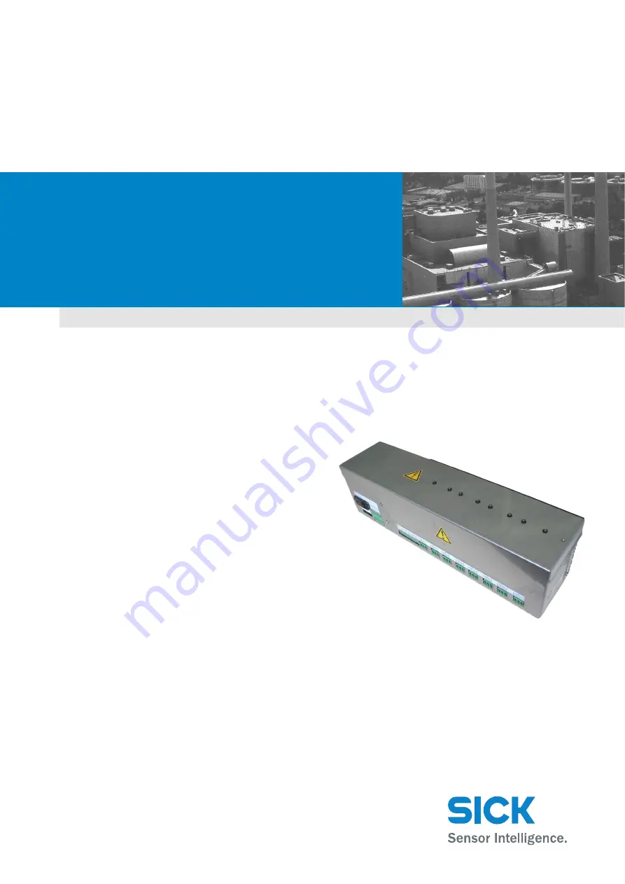
Page 14: ...sists of a microprocessor controlled regulator part with LED indication and power section for heating circuits with a 3680 VA maximum nominal rating per heating circuit Fig 1 1 HC8X Overview X10 X1 X9 X2 X3 X4 X5 X6 X7 X8 1 2 1 Special Control Unit Configuration In the full version the HC8X heat control is equipped with eight power outputs When only some of the control unit outputs are used the re...
Page 15: ...C8X heat control Note Check the respective heater mode after a control unit change Readjust as required see Chapter 4 5 Configuration and Parameter Setting with SETHC8X EXE under Win dows page 4 29 Control unit damage caused by incorrect configuration The control unit configuration may be changed only by SICK The heat control is supplied configured Changes to an existing configuration are normally...
Page 16: ...ystem cabinet For the external fusing of the supply voltage of the control electronics non heating ap paratus connection install a single pole 10 A circuit breaker see Chapter 10 2 Elec trical Data Temperatures page 10 45 near the HC8X or in the MCS 100 E measuring system cabinet 1 3 HC8X Process Connection The process connection of the HC8X e g to a MCS 100 E system is shown in Fig 3 1 Fig 1 3 HC...
Page 17: ... 1 HC8X Heat Control Product Description 8010043 SICK AG All rights reserved 1 17 1 Slide switch setting of Idle Prog or Norm modes and reset of HC8X see Chapter 5 1 1 Setting the HC8X Mode page 5 32 2 LED 1 LED 8 status signaling of the eight heating circuits 3 LED 9 LED 16 status signaling of the eight working relays 4 LED 17 LED 24 status signaling of the eight safety relays 5 Control fuses 6 L...
Page 18: ...l was previously disabled in programming mode Control function not available LED 1 LED 8 green Short blink twice per second Prog LED 25 blinks at the same rate HC8X in programming mode LED 1 LED 8 green Short blink three times per second Norm LED 25 blinks at the same rate Alarm on respective channel Error acknowledgment with slide switch or with a software reset command via the serial interface L...
Page 19: ... an I O module box and the measuring system PC may not exceed 60 m 2 2 Installing the HC8X Control unit damage by overheating Install the HC8X horizontally if possible If required install the HC8X vertically so that the ventilator on the side points downward Ensure adequate heat dissipation Install the HC8X so that the internal control unit ventilator can draw in cool air unhin dered 1 Position th...
Page 20: ...ted screws from the case cover pull off the plug connection of the grounding line and remove the case cover 6 Check whether the supply line on terminal strip X9 is free from voltage When this is the case disconnect the wires 7 Pull all plugs from terminal strips X1 to X8 8 Loosen the four attachment screws on the case base plate of the HC8X by a few turns and lift the HC8X from the attachment 9 Ch...
Page 21: ...1 Socket for mains connection with fuse holder and system voltage switch over 115 V 230 V 50 60 Hz 2 Optical fiber connection 3 X10 plug type terminal strip for PT100 temperature sensors 4 X9 plug type terminal strip for power electronics supply voltage 5 X1 X8 plug type terminal strip for heating circuits 3 2 Connecting the Power Electronics Supply Voltage Destruction of electrical components by ...
Page 22: ...into the respective plug type terminal and check firm seating Table 3 2 Pin Assignment of Single Phase Heating Circuits Wire No Term Block Pin Term Signal Function 1 X1 X8 1 L Power output 115 V 230 V 50 60 Hz 2 X1 X8 2 N Neutral conductor PE X1 X8 3 PE Protective conductor 3 3 2 Connecting Two Phase Heating Circuits Connect the two phase heating circuit to two adjacent terminal blocks e g X1 chan...
Page 23: ...onductor PE X6 3 PE Protective conductor 3 X7 1 L2 7th power output 115 V 230 V 50 60 Hz X7 2 N Neutral conductor X7 3 PE Protective conductor 4 X8 1 L3 8th power output 115 V 230 V 50 60 Hz X8 2 N Neutral conductor X8 3 PE Protective conductor 3 4 Connecting the Temperature Sensors Observe the assignment of the temperature sensors PT100 When the assignment of the temperature sensor PT100 to the c...
Page 24: ...00 Sensor input channel 7 14 PT100 Sensor input channel 7 15 PT100 Sensor input channel 8 16 PT100 Sensor input channel 8 Chapter 3 Technical Information HC8X Heat Control 3 24 SICK AG All rights reserved 8010043 Electrical Installation 3 5 Connecting the Optical Fibers 1 Connect connection MA E of HC8X with connection S of measuring system PC 2 Connect connection MA S of HC8X with connection E of...
Page 25: ...contact bridge of the supply voltage switch over 4 Reinsert the required fuses in the fuse holder With 115 V preselected voltage 2 x 0 4 AT slow blow size 5 x 20 With 230 V preselected voltage 2 x 0 2 AT slow blow size 5 x 20 5 Firmly press in the fuse holder until you hear it click into place 3 6 2 Connecting the Supply Voltage Destruction of control unit by overvoltage The control electronics of...
Page 26: ... and in tended only for trained personnel Steps for configuration and addressing Establish the communication between the measuring system PC and the HC8X Configuration and parameter setting of the HC8X with the HC8XINIT EXE MS DOS and SETHC8X EXE Windows utility programs 4 3 Parameter Setting with HC8XINIT EXE under MS DOS Control unit damage Modifications of the factory configuration and paramete...
Page 27: ...ve variable HC8XINIT max 96 chars as remark in the HC8X Option C must be defined the rest uses defaults if not specified The communication with HC8X in Prog mode runs always with 9600 Bd Example HC8XINIT c3 b1200 t120 3 a49 n6305 e123 uses the HC8X on COM3 at 9600 Bd IRQ4 8 data bits 1 stop bit no parity sets HC8X address to 49 dec control temperature to 120 3degC on channels 0 3 5 and 6 enables c...
Page 28: ...0 4 185 0 5 185 0 6 185 0 7 185 0 TLLim 0 12 0 1 12 0 2 12 0 3 12 0 4 12 0 5 12 0 6 12 0 7 12 0 TULim 0 12 0 1 12 0 2 12 0 3 12 0 4 12 0 5 12 0 6 12 0 7 12 0 THyst 0 5 0 1 5 0 2 5 0 3 5 0 4 5 0 5 5 0 6 5 0 7 5 0 Remark Chapter 4 Technical Information HC8X Heat Control 4 28 SICK AG All rights reserved 8010043 Configuration and Addressing 4 4 Parameter Setting Example with HC8XINIT EXE under MS DOS ...
Page 29: ... 12 0 7 12 0 TULim 0 12 0 1 12 0 2 12 0 3 12 0 4 12 0 5 12 0 6 12 0 7 12 0 THyst 0 5 0 1 5 0 2 5 0 3 5 0 4 5 0 5 5 0 6 5 0 7 5 0 Remark Written BaudRate 9600 Bd Address 48 dec 30 hex Function HC Correction inactive Programbl active Gain 1 00000 Offset 0 00 Channel activity 0 Enabled 1 Enabled 2 Enabled 3 Enabled 4 Disabld 5 Enabled 6 Follows 7 Follows HC Mode 0 H1 1 H1 2 H1 3 H1 4 H1 5 H1 6 H1 7 H...
Page 30: ... by the previous control channel 4 5 1 Example for Channel Following 1 Set the HC8X with the slide switch to the Prog mode see Chapter 5 1 1 Setting the HC8X Mode page 5 32 2 Start the utility program HC8XINIT EXE with parameter c1 FX X digit of respective control channel on the measuring system PC The control channel set as a follower and the previous control channel controlling chan nel have bee...
Page 31: ... that the PC board is not damaged Basic Setting Set the HC8X to the basic state 1 Switch off the supply voltage of the HC8X control electronics 2 Push the slide switch see Fig 1 4 page 1 17 to position B 3 Switch on the supply voltage of the HC8X control electronics LED25 acknowledges with a single short blink 4 Push the slide switch to position A again After the successful transfer of the preset ...
Page 32: ... than 5 s a switch over to the Idle mode is made auto matically Norm 2 B A Short blink once per second HC8X is inactive Idle 3 A B A Short blink twice per second HC8X expects parameters from the measuring system PC or sends data to the measuring sys tem PC on request Prog 4 A B A Continuous signal or Short blink three times per second HC8X works as a two position controller Alarm on at least one c...
Page 33: ...cs Supply Voltage page 3 21 9 Check the preset value of the supply voltage to the control electronics in the indicator window of the socket 10 If the set voltage differs from the required voltage Preselect the supply voltage see Chapter 3 6 1 Supply Voltage and Fuse Preselection Primary Side page 3 25 11 Check the optical fiber connection of the HC8X see Chapter 3 5 Connecting the Optical Fibers p...
Page 34: ...HEN HON HEN HON Heizungsart H1 Heizungsart T 1 Heizungsart B1 ALR Alert Alarm ERR Error Error HEN Heating Enabled Heater safety relay HON Heating On Heater working relay TAB Temperature Above Hysteresis Band Temperature req temp hyst TBB Temperature Below Hysteresis Band Temperature req temp hyst THI Temperature High Temperature req temp upper limit TLO Temperature Low Temperature req temp lower l...
Page 35: ... when the HC8X is switched off 1 Switch off the supply voltage of the power electronics terminal strip X9 and secure it against switching on again 2 Switch off the supply voltage of the control electronics and pull the plug from the mains socket 6 2 Switching the HC8X on Again 1 Insert the plug in the mains socket of the HC8X and switch on the supply voltage of the control electronics 1 Switch on ...
Page 36: ...ive parts Disconnect all poles of the power section and control section from the supply voltage before opening the control unit Check whether the power section and the control section are free from voltage 1 Unscrew two screws from the case cover 2 Remove the case cover and pull off the ground conductor 3 Find the next free installation area in the control unit 4 Position the load relay on the hea...
Page 37: ...nd of the wiring marked REL onto the flat plug connection on the load relay Fig 7 1 Wiring on the Flat Plug Connection of Printed Circuit Board and Load Relay Note Observe mains symmetry 10 Push the end of the wiring marked BR onto the flat plug connection of the conductor bar see Fig 7 2 page 7 37 11 Push the end of the wiring marked 1 onto the flat plug connection of the thermally de layed overc...
Page 38: ...age 3 22 17 Configure address the respective power channel see Chapter 4 Configuration and Ad dressing page 4 26 18 Connect the ground line with flat plug contact in the case cover and check correct seat ing 19 Close and screw on the case cover 20 Connect the supply voltage to all poles 21 Put the HC8X in operation see Chapter 5 Start up page 5 31 7 1 2 Retrofitting the HC8X with an Odd Number of ...
Page 39: ...rs Danger of electrical shock Do not touch live parts Disconnect all poles of the power section and control section from the supply voltage before opening the case Check whether the power section and the control section are free from voltage Change the outer conductor connections only on the L1 L2 or L3 conductor bars Changing the outer conductor connections on the conductor bars see Fig 7 4 page ...
Page 40: ...l Information HC8X Heat Control 7 40 SICK AG All rights reserved 8010043 Retrofitting Conductor Bar Configuration 8 Put the HC8X in operation see Chapter 5 Start up page 5 31 Fig 7 4 Position of the Outer Conductor Bars ...
Page 41: ...k the fuse holder with a screwdriver on the side tongue and pull it out 2 Pull out the contact bridge of the supply voltage switch over and turn it so that the de sired voltage rating is visible in the indicator window of the mains socket e g 115 3 Reinsert the contact bridge of the supply voltage switch over 4 Reinsert the required fuses in the fuse holder With 115 V preselected voltage 2 x 0 4 A...
Page 42: ...perature of the control unit is Tmax 50 C the safety temperature switch switches off the power section The communication between the measuring system PC and the I O units is maintained After the temperature has significantly cooled by at least 10 K the heat control is enabled again Fig 8 1 Arrangement of the Fuses and the Over Temperature Protection SI3 SI2 SI1 2 3 1 1 Secondary side fuses of the ...
Page 43: ... Disposal after Final Shut Down Dispose of unusable or irreparable control units in an environmentally compatible manner and according to the specific waste disposal regulations of your country The design of the HC8X allows for the separation into reusable secondary raw materials and special waste electronics waste ...
Page 44: ...ts reserved 8010043 Technical Data Annex 10 Technical Data Annex 10 1 Dimensions General Data Fig 10 1 HC8X Case Dimensions 588 140 160 Fig 10 2 Attachment Dimensions 564 71 109 Control unit Type Case version Stainless steel 1 4301 Weight Approx 10 kg Table 10 1 General Data ...
Page 45: ...of control electronics primary side With 115 V AC 2 x 0 4 A slow blow 5 x 20 mm With 230 V AC 2 x 0 2 A slow blow 5 x 20 mm External back up fuse connection 10 A max External back up fuse of power electronics 3 x 35 A max Temperature sensors PT100 Power supply of temperature sensors 0 8 mA Conductor cross section of temperature sensors X10 0 2 2 5 mm2 single or multi wire Conductor cross section o...
Page 46: ...INIT EXE after the Call Up without Additional Parameters 27 Fig 4 2 Configuration Output of HC8XINIT EXE 28 Fig 4 3 Parameter Setting Example with Output of the Environment Variable 29 Fig 5 1 Control Process 34 Fig 7 1 Wiring on the Flat Plug Connection of Printed Circuit Board and Load Relay 37 Fig 7 2 Wiring on Conductor Bar and Overcurrent Trip 37 Fig 7 3 Wiring on Overcurrent Trip and Load Re...
Page 47: ...y Voltage 22 Table 3 2 Pin Assignment of Single Phase Heating Circuits 22 Table 3 3 Pin Assignment of Two Phase Heating Circuits 22 Table 3 4 Pin Assignment of Three Phase Heating Circuits 23 Table 3 5 Pin Assignment of the 2 Pole Temperature Sensor Connections 24 Table 5 1 Preset Values 31 Table 5 2 Setting the Mode with the Slide Switch 32 Table 10 1 General Data 44 Table 10 2 Electrical Data 45...
Page 48: ...16 H H1 14 Heat control 15 Heating circuit states 16 Heating ENable 16 Heating Enabled 34 Heating modes 14 Heating ON 16 34 HEN 16 34 HON 16 34 L LED 16 LED 25 17 List of Tables 47 Load distribution 39 Load relay 36 Load symmetry 15 M MCS 100 E 16 Mode 16 O Optical fiber connection 21 Overcurrent Protective Device 36 41 P Printed circuit board 17 Process connection 16 R Red LED 16 Removal Procedur...
Page 49: ...Technical Information HC8X Heat Control 8010043 SICK AG All rights reserved E 49 ...
Page 50: ...AG Waldkirch Germany www sick com 8010043 V 1 1 2013 01 Subject to change without notice SICK worldwide You will find our local subsidiary or agency at www sick com Your local sales and service partner HC8X ...