


10.2.2
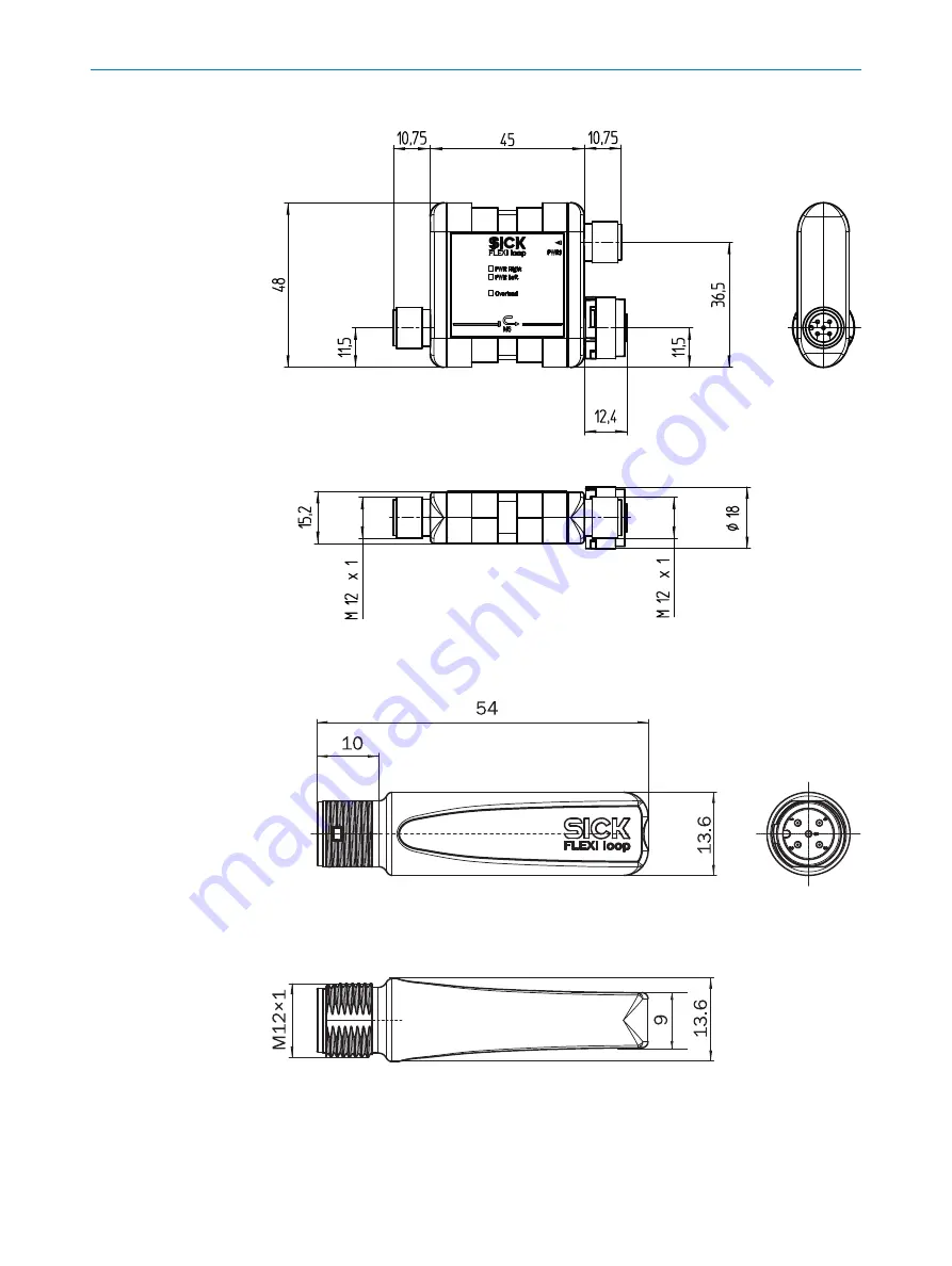
Dimensional drawing PWRI power supply accessory
Figure 71: Dimensional drawing PWRI power supply accessory (mm)
10.2.3
Dimensional drawing terminator
Figure 72: Dimensional drawing Flexi Loop termination element (mm)
10
TECHNICAL DATA
88
O P E R A T I N G I N S T R U C T I O N S | Flexi Loop
8015836/YT10/2016-05-24 | SICK
Subject to change without notice


