background image

Table 6: Warnings

Diagnostics LED

Color

Meaning

1 ... 8

O

 Yellow

A yellow illuminated diagnostic LED signals
which function is affected.

1 ... 8

Ö

 Yellow

A yellow flashing diagnostic LED signals the
reason for the warning.

o

 LED off. 

Ö

 LED flashes. 

O

 LED illuminates.

Example: If diagnostic LED 5 lights up yellow and diagnostic LED 3 flashes yellow, the
sensor gap monitoring was exceeded.

Further topics

"Diagnostic LEDs", page 77

3.3

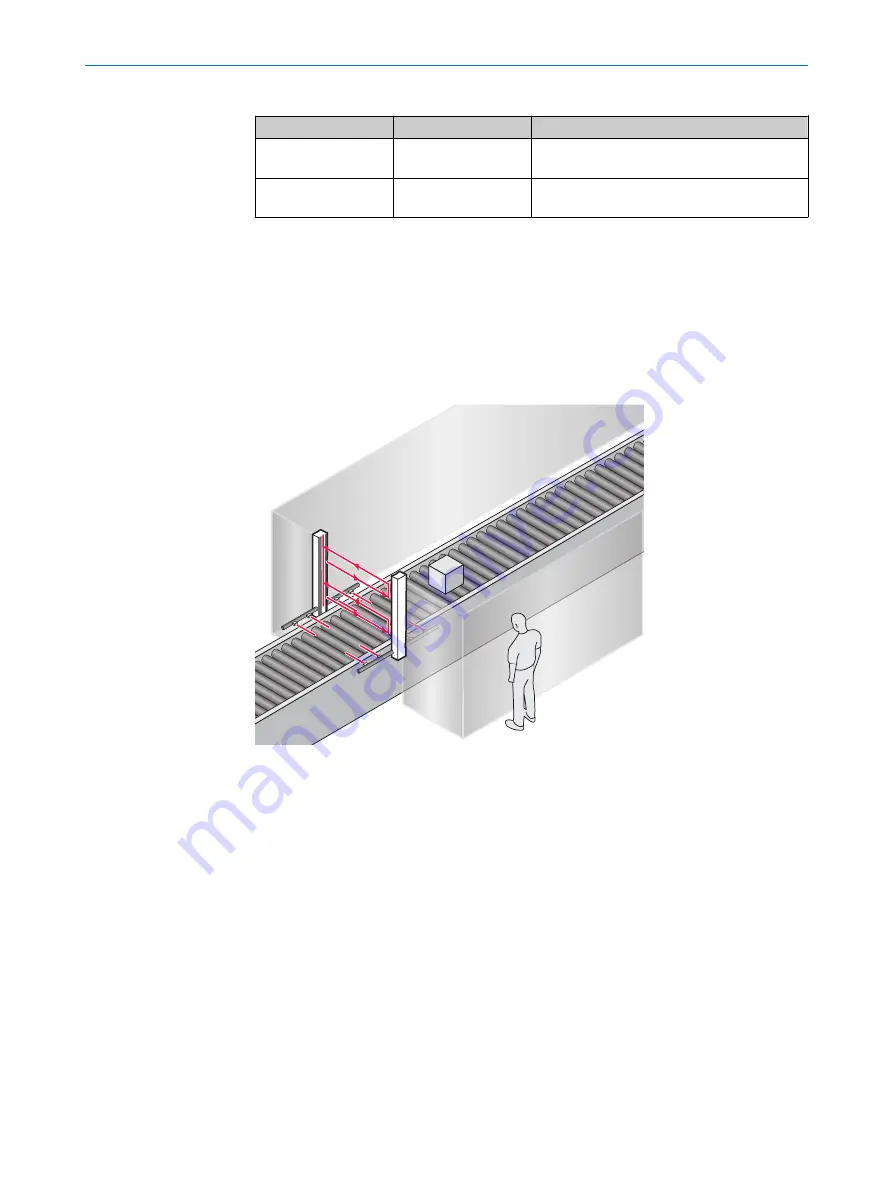
Example applications

Figure 7: Access protection

PRODUCT DESCRIPTION 

3

8024802/2020-07-17 | SICK

O P E R A T I N G   I N S T R U C T I O N S | deTem4 LT Muting A/P

17

Subject to change without notice

Summary of Contents for deTem4 LT Muting A/P

Page 1: ...O P E R A T I N G I N S T R U C T I O N S deTem4 LT Muting A P Multiple light beam safety device...

Page 2: ...sible within the limits of the legal determination of Copyright Law Any modifica tion abridgment or translation of this document is prohibited without the express writ ten permission of SICK AG The tr...

Page 3: ...8 Near Field Communication NFC 14 3 2 9 Status indicators 15 3 3 Example applications 17 4 Project planning 18 4 1 Manufacturer of the machine 18 4 2 Operating entity of the machine 18 4 3 Design 19 4...

Page 4: ...uring beam coding 60 7 5 Configuring the C1 muting release 61 7 6 Configuring muting 61 7 7 Configuring the restart interlock 62 7 8 Configuring application diagnostic output 63 8 Commissioning 64 8 1...

Page 5: ...91 14 Ordering information 94 14 1 Scope of delivery 94 14 2 Ordering information 94 15 Accessories 96 15 1 Brackets 96 15 2 Mounting accessories 97 15 3 Weld spark guard 97 15 4 Connectivity 98 15 5...

Page 6: ...ng instructions are relevant for intended use of the product Table 1 Target groups and selected chapters of these operating instructions Target group Chapters of these operating instructions Project d...

Page 7: ...ation presenting possible danger which may lead to property damage if not prevented NOTE Indicates useful tips and recommendations Instructions to action b The arrow denotes instructions to action 1 T...

Page 8: ...ion from pieces thrown from application nor from emitted radiation Transparent objects are not detected Among others the multiple light beam safety device is not suitable for the following application...

Page 9: ...aspects Operation and maintenance For operation and maintenance a person is considered competent when he she has the expertise and experience in the relevant field and is sufficiently familiar with th...

Page 10: ...e or its control must safely analyze the signals for example using a safe control or safety relays and stop the dangerous state The deTem4 LT Muting A P multiple light beam safety device is used for m...

Page 11: ...y using a weld spark guard Further topics Data sheet page 87 Weld spark guard page 97 3 2 Product characteristics 3 2 1 Device overview Figure 2 Overview of the active unit End cap with integrated LED...

Page 12: ...ection for muting signal A Connection for muting signal B Connection for reset override pushbutton e g ER12 System connection Muting arm A Muting arm B Muting sensors 3 PRODUCT DESCRIPTION 12 O P E R...

Page 13: ...ms distant from the system connection are indicated via the diagnostic LEDs 5 8 3 2 4 Restart interlock The multiple light beam safety device has an integrated restart interlock The function can be co...

Page 14: ...se function can be configured during commissioning and is located at In4 of the system connec tion The C1 muting release function is a supplementary signal from an external source that is only used fo...

Page 15: ...Overview The LEDs of the active unit signal the operational status of the multiple light beam safety device 1 2 3 4 5 6 7 8 OSSD INFO Figure 6 Status indicators of the active unit Position LED color...

Page 16: ...D flashes O LED illuminates Table 4 Indication of the alignment quality Diagnostics LEDs Color Meaning 1 4 O Blue Display of alignment quality of the beams close to the system connection If only one d...

Page 17: ...arning o LED off LED flashes O LED illuminates Example If diagnostic LED 5 lights up yellow and diagnostic LED 3 flashes yellow the sensor gap monitoring was exceeded Further topics Diagnostic LEDs pa...

Page 18: ...he protective func tion Do not carry out any repairs on the device components 4 2 Operating entity of the machine DANGER Hazard due to lack of effectiveness of the protective device Persons and parts...

Page 19: ...c ballast installed in the path of the beam or beams from laser pointers directed at the active unit b If this type of light radiation is present in the environment of the protective device take addit...

Page 20: ...chnical data page 87 4 3 2 1 Calculating minimum distance from the hazardous point Important information DANGER Minimum distance from the hazardous point is too small The dangerous state of the machin...

Page 21: ...0 ms 20 ms 310 ms 0 31 s S 1 600 mm s 0 31 s 850 mm 1 346 mm 4 3 3 Minimum distance from reflective surfaces Overview The light beams from the active unit may be deflected by reflective surfaces and d...

Page 22: ...unit outside the maximum scanning range of 7 m system with 4 beams that could cause beam deflection Determining minimum distance to reflective surfaces 1 Determine the distance between active and pas...

Page 23: ...that the opera tor is at risk Figure 12 Upset condition 2 Preventing mutual interference from system and system Upset condition 2 The infrared light beams of the active units of systems and can cause...

Page 24: ...rouble free operation due to beam coding In the figure the beam coding of systems in close proximity to each other is different This means that the systems do not influence each other Complementary in...

Page 25: ...red by at least 2 signals wired independently of each other e g by muting sensors Muting must not depend entirely on software signals e g from a PLC Muting must be reversed after the material has pass...

Page 26: ...muting sensors or reflectors and the ESPE is changed the distance between the two muting sensors or reflectors on a muting arm needs to be checked also In the recommended mounting position of the mut...

Page 27: ...s and a muting end delay of 0 2 s has elapsed If a muting sensor is clear sensor gap monitoring will expire meaning that a mut ing sensor may not be clear longer than 0 5 s If the sensor gap monitori...

Page 28: ...and detect the material before it passes through the ESPE The material can be transported either into the hazardous area or out of the hazardous area A1 L1 L3 A2 B1 B2 L2 Figure 15 Entry exit monitori...

Page 29: ...as an internal muting release The C1 muting release function can be configured during commissioning and is located at In4 of the system connec tion The C1 muting release function is a supplementary si...

Page 30: ...control switch Performing an override with the integrated override function An error occurs while a muting condition is valid The cause of the error is indicated by the LEDs on the active unit If an...

Page 31: ...activated muting signal continues to be interpreted as an active signal and muting is maintained Muting is only ended if one of the muting sensors is clear for longer than 0 5 s The following applies...

Page 32: ...s no longer engaged and the sensor gap monitoring of 0 5 s has been exceeded the muting hold time of 4 s begins ESPE protection is bypassed within this time period and material or a means of transport...

Page 33: ...t stopped in a timely manner b Make sure that the following control and electrical requirements are met so that the multiple light beam safety device can fulfill its protective function It must be pos...

Page 34: ...ective device In the case of non compliance it is possible that the dangerous state of the machine may not be stopped or not stopped in a timely manner Downstream contactors must be positively guided...

Page 35: ...ulations which apply at the place of installation a restart interlock may be required Important information DANGER Hazard due to unexpected starting of the machine The machine may not restart if the O...

Page 36: ...it when the light path is clear the OSSDs switch to the ON state The machine may not restart yet The operator must also press the machine start button after having pressed the reset pushbutton Facili...

Page 37: ...d a light can be connected to the application diagnostic output or the signal can be transmitted to the machine con troller 0 V DC ADO Figure 22 Electrical diagram of the application diagnostic output...

Page 38: ...he RLY3 OSSD2 and override on the deTem4 LT Muting A P 1 Output circuits These contacts must be incorporated into the control such that the dan gerous state is brought to an end if the output circuit...

Page 39: ...DC K2 K1 R1 Y1 Y2 24 A2 14 S1 I1 I2 23 A1 13 RLY3 OSSD2 k2 z k1 k2 k1 z x y x 1 y 2 PELV F0 Muting sensor pair B Muting sensor pair A C1 Muting enable ER12 H1 RES OVR Q k2 k1 Figure 24 Connection dia...

Page 40: ...eck during commissioning and modifications Regular thorough check Thorough check during commissioning and modifications The test is intended to ensure that the hazardous area is monitored by the prote...

Page 41: ...m safety device do not affect the machine during the check DANGER Hazard due to lack of effectiveness of the protective device Persons and parts of the body to be protected may not be recognized in ca...

Page 42: ...front of the passive unit 4 5 2 Visual check of the machine and the protective device The following points are often helpful for the definition of the check Has the machine been retrofitted Have machi...

Page 43: ...ged cables or open cable ends If one of the points applies the machine should be shut down immediately In this case the machine and the protective device must be checked by appropriately qualified saf...

Page 44: ...n and shock specifica tions exceed the values and test conditions specified in the data sheet DANGER Hazard due to lack of effectiveness of the protective device Persons and parts of the body to be pr...

Page 45: ...ds to be replaced The procedure describes the recommended mounting position of the muting arms at the height of the lowest light beam of the ESPE Approach 1 Unpack the pre mounted muting arms 2 Remove...

Page 46: ...m bracket Secure both connecting cables of a muting sensor pair together when doing so Clamp the connecting cables first at the lower hook of the muting arm bracket and then at the upper hook of the m...

Page 47: ...7 Lay the connecting cables over the muting arms MOUNTING 5 8024802 2020 07 17 SICK O P E R A T I N G I N S T R U C T I O N S deTem4 LT Muting A P 47 Subject to change without notice...

Page 48: ...ot be recognized or not recognized in time in case of non observance b Take account of the minimum distances calculated for the machine see Mini mum distance from the hazardous point page 19 see Minim...

Page 49: ...the device is exposed to strong vibrations during operation mount the top bracket at a height where the offset in the multiple light beam safety device housing rests on the bracket b Tightening torque...

Page 50: ...ing the QuickFix bracket Overview The active and passive units are each mounted using 2 QuickFix brackets The QuickFix bracket consists of 2 individual parts that are pushed into each other The two in...

Page 51: ...the QuickFix bracket mounting method Description On the side 1 Fasten the M5 screw to the machine or profile frame through the QuickFix bracket A screw nut or threaded hole is required on the machine...

Page 52: ...f this does not impair the function Important information NOTICE The housing of the multiple light beam safety device can become scratched if the screw heads protrude when the FlexFix brackets are mou...

Page 53: ...le frame 1 If the bracket is attached at the side no muting arms can be mounted on the protective device Figure 26 Mount FlexFix bracket to a profile frame Approach 1 If no muting arms are mounted Aft...

Page 54: ...the front 3 Align the active and passive units 4 Use an M5 screw to secure the position of the active and passive unit in the Flex Fix bracket Further topics Alignment of the active and passive units...

Page 55: ...nals sepa rately DANGER Hazard due to lack of effectiveness of the protective device The dangerous state may not be stopped in the event of non compliance b Prevent the formation of a potential differ...

Page 56: ...ut signal switching devices that then also switch if controlled with negative voltage e g electro mechanical contactor without reverse polarity protection diode you must connect the 0 V con nections o...

Page 57: ...electrical control system page 33 6 3 Reset override pushbutton connection M12 5 pin 2 1 4 3 5 Figure 30 Reset override pushbutton connection female connector M12 5 pin The reset override pushbutton c...

Page 58: ...onnecting cables of a muting sensor pair This may result in the muting no longer being dependent on two independently wired signals b Do not connect any extension cables to the connecting cables of a...

Page 59: ...ation is different from the system configuration a configuration error is reported b The device must be reset to the factory settings to change the muting or the beam coding configuration b Then ensur...

Page 60: ...tive unit Configuration mode is active When resetting the active unit to the factory settings C1 muting release has been configured The reset pushbutton was pressed in order to configure the restart i...

Page 61: ...correctly Configuring the C1 muting release NOTE Skip the first and second steps if the device is already in configuration mode 1 Disconnect the device from the voltage supply 2 Switch on the voltage...

Page 62: ...ushbutton is connected The device is not in the override or override required status Approach NOTE Skip the first and second steps if the device is already in configuration mode 1 Disconnect the devic...

Page 63: ...uting status Override required Reset required When the protective device is free again after an interruption the application diagnostic output signals that the reset pushbutton needs to be pressed The...

Page 64: ...e the machine with a perfectly functioning protective device DANGER Hazard due to lack of effectiveness of the protective device Persons and parts of the body to be protected may not be recognized in...

Page 65: ...The configuration of the device is then displayed via the diagnostic LEDs and the INFO LED or the signal lamp After initialization the blue diagnostic LEDs indicate the alignment quality The alignmen...

Page 66: ...ly with the passive unit so that as many diagnostic LEDs as possible light up on the active unit 6 If necessary align the passive unit more precisely with the active unit so that as many diagnostic LE...

Page 67: ...Prerequisites A FlexFix bracket or replacement bracket has been used to mount each active and passive unit Alignment with the FlexFix bracket or with the replacement bracket The FlexFix bracket or rep...

Page 68: ...gth of the two light beams close to the system connection is still insufficient for stable availability O Blue O Blue O Blue o The alignment of the two light beams close to the system connection is go...

Page 69: ...re is a possibility that diagnostic LED 4 or diagnostic LED 8 does not light up even with optimal alignment Further topics Diagnostic LEDs page 77 8 5 Check during commissioning and modifications The...

Page 70: ...fectiveness of the protective device must be checked following such work DANGER Hazard due to lack of effectiveness of the protective device Persons and parts of the body to be protected may not be re...

Page 71: ...and that unprotected access to the hazardous area is prevented b Carry out the checks according to the instructions from the manufacturer of the machine and from the operating entity OPERATION 9 8024...

Page 72: ...ation If a function is configured the correspond ing diagnostic LED lights up O Red Yellow green o o o o o o o o Yellow green Reset of the configuration to factory set tings is activated O Green O Gre...

Page 73: ...ight path is interrupted At least one muting sensor is engaged The muting condition is not met Override required O Red Red yellow Yel low o o Yel low O Yellow o o o Red yellow The light path is interr...

Page 74: ...opics Indication of the alignment quality page 68 Diagnostic LEDs page 77 9 OPERATION 74 O P E R A T I N G I N S T R U C T I O N S deTem4 LT Muting A P 8024802 2020 07 17 SICK Subject to change withou...

Page 75: ...GER Hazard due to lack of effectiveness of the protective device Persons and parts of the body to be protected may not be recognized in case of non observance b Regularly check the degree of contamina...

Page 76: ...ber 4003353 Approach 1 Remove dust from the front screen using a soft clean brush 2 Then wipe the front screen with a clean damp cloth 3 Check the alignment of the active and passive units 4 Check the...

Page 77: ...rly identified b Immediately put the machine out of operation if you cannot clearly identify or allo cate the fault and if you cannot safely remedy the fault b Secure the machine so that it cannot swi...

Page 78: ...oring is configured O White O White Entry exit monitoring is configured O White C1 muting release is configured O Red Yellow green o o o o o o o o Yellow green Reset of the configuration to factory se...

Page 79: ...ce the protective device is aligned and the light path is clear INFO LED flashing yellow or lit up green the alignment quality display switches off after a certain period of time TROUBLESHOOTING 11 80...

Page 80: ...muting release is configured O Red Green Green The device is in configuration mode follow ing a change to the configuration If a function is configured the correspond ing diagnostic LED lights up O R...

Page 81: ...exceeded during exit monitoring One muting sensor is still engaged Override required O Red Red yellow o o Yel low o O Yellow o o o Red yellow The light path is interrupted The sensor gap monitoring ha...

Page 82: ...rride required o LED off LED flashes O LED illuminates Empty cells mean that the LED lights up flashes or is off If front screen contamination increases in ongoing operation or the alignment is poor f...

Page 83: ...Red Red o Red o o o o o o Red Fault in the voltage sup ply b Check the voltage supply and the power supply unit see Technical data page 87 b Switch the voltage supply off and back on again b If the fa...

Page 84: ...rectly see Integration in the electrical con trol system page 33 b Switch the voltage supply off and back on again b If the fault continues to persist replace the defective compo nents see Ordering in...

Page 85: ...ompartment of the active unit b Switch off the voltage supply b Connect the connecting cables of the muting sensor pairs to the active unit b Switch the voltage supply back on o LED off LED flashes O...

Page 86: ...cordance with national waste disposal regulations Complementary information SICK will be glad to help you dispose of these devices on request 12 DECOMMISSIONING 86 O P E R A T I N G I N S T R U C T I...

Page 87: ...ime 24 h 1 If the light path is very long there is a possibility that all diagnostic LEDs 1 4 or 5 8 will not light up even when alignment is optimal 2 The minimum scanning range specifies a range in...

Page 88: ...30 C 70 C Housing cross section of the active unit and the passive unit for small scanning ranges 31 mm 34 mm plus bracket see Dimensional draw ings page 91 Weight see Table of weights page 90 Vibrat...

Page 89: ...y cable 2 Cable between OSSD and load 2 5 All additional wires at the system connection and the reset override pushbutton connection 2 5 1 Applies to the voltage range between 30 V and 30 V 2 Accordin...

Page 90: ...mber of beams Weight in g 1 4 1315 1 Tolerance 50 g Table 29 Weight of the active unit with integrated LED and two muting arms Number of beams Weight in g 1 4 1460 1 Tolerance 50 g Table 30 Weight of...

Page 91: ...pin L 76 8 31 79 6 56 8 80 2 8 30 7 29 5 31 1 7 8 6 2 4 5 3 1 2 4 5 3 1 2 4 5 3 Figure 34 Dimensional drawing of active unit Table 33 Dimensions of the active unit Number of beams Beam separation dime...

Page 92: ...unit for short scanning range Table 34 Dimensions passive unit for short scanning range Number of beams Beam separation dimension S in mm Length dimension L in mm 4 300 1072 13 TECHNICAL DATA 92 O P...

Page 93: ...2 68 2 100 100 875 Passive Side Active Side 31 5 12 max 25 18 2 16 9 7 32 9 7 Figure 36 Dimensional drawing for active and passive unit with muting arms mounted TECHNICAL DATA 13 8024802 2020 07 17 S...

Page 94: ...tive unit Type code Part number 4 M4M ZA04300D20 1096014 Table 36 Ordering data of passive unit for short scanning range Number of beams Passive unit Type code Part number 4 PSN02 2301 1102144 Table 3...

Page 95: ...cket for mount ing on the left side of the pas sive unit plus 4 FlexFix brack ets 1108691 T muting entry exit monitor ing Set comprising one active unit with two pre mounted muting arms including four...

Page 96: ...66614 QuickFix bracket 2x BEF 3SHABPKU2 2066048 QuickFix bracket 4x BEF 3SHABPKU4 2098710 FlexFix bracket 5 2 10 4 53 8 7 13 21 8 3 5 49 31 5 30 41 1 29 7 3 7 5 2 10 2 31 5 Figure 37 Dimensional drawi...

Page 97: ...ard for short scanning ranges The weld spark guard reduces the scanning range of the system as follows Weld spark guard on the active unit and the passive unit for short scanning ranges The system sca...

Page 98: ...cable flying leads YF2A18 150UA5XLEAX 2095679 Female connector straight 20 m cable flying leads YF2A18 200UA5XLEAX 2095680 Female connector angled 2 m cable flying leads YG2A18 020UA5XLEAX 2095779 Fe...

Page 99: ...onnector straight YF2A15 100UB5M2A15 2096011 Table 44 Protective cap ordering information Part Part number Protective cap M12 for female connector 5310772 Table 45 Ordering information for reset pushb...

Page 100: ...45 Table 53 Ordering data of muting arms Part Part number Muting arm with mounted muting sensors for active unit 2109381 Muting arm with mounted reflectors for passive unit 2109753 T muting arm with m...

Page 101: ...other Table 54 Ordering details bracket for muting arms Part Part number Muting arm bracket 2106455 Table 55 Ordering details cable cover for muting arm Part Part number Cable cover for muting arm lo...

Page 102: ...cifications stated in the EU declaration of conformity have been used as a basis for this Complete EU declaration of conformity for download You can call up the EU declaration of conformity and the cu...

Page 103: ...423 10 IEC 60068 2 27 GB T 2423 5 IEC 60204 1 GB 5226 1 IEC 60529 GB T 4208 IEC 60825 1 GB 7247 1 IEC 61131 2 GB T 15969 2 IEC 61140 GB T 17045 IEC 61496 1 GB T 19436 1 IEC 61496 2 GB T 19436 2 IEC 61...

Page 104: ...additional mechanical protective measures fitted and secured against manipulation which prevent reaching below above or around the ESPE Yes No Has the maximum shutdown and or stopping time of the mach...

Page 105: ...36 22 Electrical diagram of the application diagnostic output 37 23 Connection diagram with restart interlock and external device monitoring on the RLY3 OSSD2 and override on the deTem4 LT Muting A P...

Page 106: ...integrated LED and one muting arm 90 29 Weight of the active unit with integrated LED and two muting arms 90 30 Weight of passive unit for short scanning range 90 31 Weight of the passive unit for sh...

Page 107: ...arms 101 55 Ordering details cable cover for muting arm 101 56 Note on specified standards 103 LIST OF TABLES 18 8024802 2020 07 17 SICK O P E R A T I N G I N S T R U C T I O N S deTem4 LT Muting A P...

Page 108: ...8080 7425 E Mail enquiry my sick com Mexico Phone 52 472 748 9451 E Mail mexico sick com Netherlands Phone 31 0 30 229 25 44 E Mail info sick nl New Zealand Phone 64 9 415 0459 0800 222 278 tollfree...

Reviews: