background image

Operating Instructions

Chapter 

11


C 4000

56

©

 SICK AG • Safety Systems • Germany • All rights reserved

8 009 221/16-11-00

Ordering information

11.3.2

Cascadable system with function package B

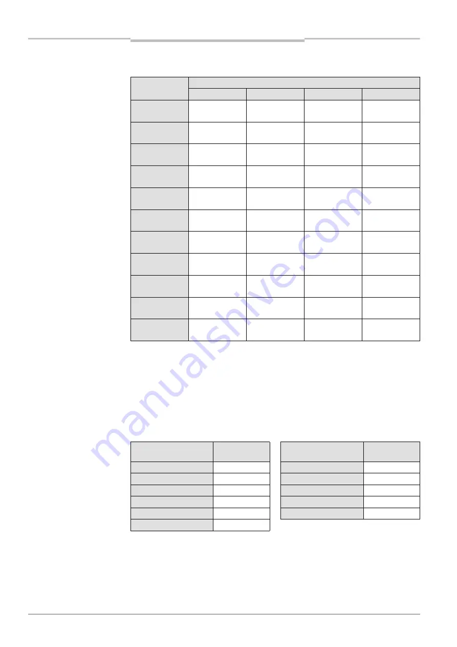
11.4 Additional front screen (welding spark guard)

Notes

·

One additional front screen (welding spark guard) supplied for each part number.

·

The additional front screen fits both on the sender and on the receiver.

·

The additional front screen may be used only if the curved enclosure side is accessible.

·

An additional front screen reduces the scanning range of the system by 8%. If sender and 
receiver each use an additional front screen, the scanning range will be reduced by 16%.

Protective field 

height [mm]

Part numbers for resolution

14 mm

20 mm

30 mm

40 mm

300

I

1 018 690

H

1 018 827

I

1 018 710

H

1 018 838

I

1 018 733

H

1 018 849

I

1 018 755

H

1 018 860

450

I

1 018 349

H

1 018 828

I

1 018 712

H

1 018 839

I

1 018 735

H

1 018 850

I

1 018 757

H

1 018 861

600

I

1 018 692

H

1 018 829

I

1 018 714

H

1 018 840

I

1 018 737

H

1 018 851

I

1 018 759

H

1 018 862

750

I

1 018 694

H

1 018 830

I

1 018 716

H

1 018 841

I

1 018 739

H

1 018 852

I

1 018 762

H

1 018 863

900

I

1 018 696

H

1 018 831

I

1 018 718

H

1 018 842

I

1 018 741

H

1 018 853

I

1 018 765

H

1 018 864

1050

I

1 018 698

H

1 018 832

I

1 018 720

H

1 018 843

I

1 018 743

H

1 018 854

I

1 018 767

H

1 018 865

1200

I

1 018 700

H

1 018 833

I

1 018 722

H

1 018 844

I

1 018 745

H

1 018 855

I

1 018 769

H

1 018 866

1350

I

1 018 702

H

1 018 834

I

1 018 724

H

1 018 845

I

1 018 747

H

1 018 856

I

1 018 771

H

1 018 867

1500

I

1 018 704

H

1 018 835

I

1 018 726

H

1 018 846

I

1 018 749

H

1 018 857

I

1 018 773

H

1 018 868

1650

I

1 018 706

H

1 018 836

I

1 018 728

H

1 018 847

I

1 018 751

H

1 018 858

I

1 018 775

H

1 018 869

1800

I

1 018 708

H

1 018 837

I

1 018 730

H

1 018 848

I

1 018 753

H

1 018 859

I

1 018 777

H

1 018 870

Tab. 26: Part numbers, 

cascadable system with 

function package B

Protective 

field height [mm]

Part number

Protective 

field height [mm]

Part number

300

2 022 412

1200

2 022 418

450

2 022 413

1350

2 022 419

600

2 022 414

1500

2 022 420

750

2 022 415

1650

2 022 421

900

2 022 416

1800

2 022 422

1050

2 022 417

Tab. 27: Part numbers, 

additional front screen 

(welding spark guard)

Summary of Contents for C 4000 Series

Page 1: ...O P E R A T I N G I N S T R U C T I O N S S a f e t y L i g h t C u r t a i n C 4 0 0 0 ...

Page 2: ...Operating Instructions C 4000 2 SICK AG Safety Systems Germany All rights reserved 8 009 221 16 11 00 ...

Page 3: ...Operating Instructions C 4000 8 009 221 16 11 00 SICK AG Safety Systems Germany All rights reserved 3 ...

Page 4: ...e 12 3 4 Configurable functions 12 3 4 1 Restart interlock 13 3 4 2 External device monitoring EDM 14 3 4 3 Beam coding 14 3 4 4 Scanning range 15 3 4 5 Fixed blanking 16 3 4 6 Floating blanking 17 3 4 7 Reduced resolution 19 3 5 Indicator elements 20 3 5 1 Operation status indicators of the sender 20 3 5 2 Indicator elements of the receiver 21 4 Installation and mounting 22 4 1 Determining the sa...

Page 5: ... 10 1 Data sheet 43 10 2 Response time 45 10 3 Table of weights 47 10 4 Dimensional drawings 48 10 4 1 Standard system not cascadable 48 10 4 2 Cascadable system 49 10 4 3 Swivel mount bracket 50 10 4 4 Side mounting 50 10 4 5 Deflector mirror 51 11 Ordering information 52 11 1 Delivery 52 11 2 Standard system 53 11 2 1 Standard system without function package 53 11 2 2 Standard system with functi...

Page 6: ...eral safety light curtains C 4000 It also addresses persons who integrate the C 4000 into a machine initialize its use or who are in charge of servicing and maintaining the unit 1 3 Information depth These operating instructions contain information on of the safety light curtain C 4000 Planning and using safety devices such as the C 4000 also require specific technical skills which are not conveye...

Page 7: ...aking action are shown by an arrow Carefully read and follow the instruc tions for action WARNING Warning notice A warning notice indicates an actual or potential risk or health hazard They are designed to help you to prevent accidents Carefully read and follow the warning notices n Software notes show the location in the CDS Configuration Diagnosis Software where you can make the appropriate sett...

Page 8: ... by IEC 61496 1 and 2 and is therefore allowed for use with controls in safety category 4 in compliance with EN 954 The device is suitable for Hazardous point protection finger and hand protection Hazardous area protection Access protection Access to the hazardous area must be allowed only through the protective field The plant system is not allowed to start as long as personnel are within the haz...

Page 9: ...documented to ensure that the tests can be recon structed and retraced at any time The operating instructions must be made available to the user of the machine where the safety light curtain C 4000 is fitted The machine operator is to be instructed in the use of the device by specialist personnel and must be instructed to read the operating in structions The external voltage supply of the device m...

Page 10: ...ne integrated restart interlock Connecting options for the reset button External device monitoring EDM Beam coding Status display with 7 segment display Optional Function package B Blanking several areas Blanking with tolerance of up to 2 beams Floating blanking Reduced resolution Monitoring the blanked area 3 2 Mode of function of the device 3 2 1 Components of the device Fig 1 Components of the ...

Page 11: ...ver automatically synchronize themselves optically An electrical connec tion between both these components is not required The C 4000 is modular in structure All optical and electronic components and assemblies are housed in a slim and torsionally rigid housing 3 2 3 Cascading To provide an effective point of operation guard a maximum of three C 4000 can be con nected in series for cascading confi...

Page 12: ...t cannot be operated by a person working inside the hazardous area The statutory and local rules and regulations must be observed when installing and using the device 3 4 Configurable functions This chapter describes the functions of the safety light curtain C 4000 selectable via soft ware Some of the functions can be combined WARNING Test the protective device after any changes The entire protect...

Page 13: ... restart interlock the users and oper ators of the machine will be at an acute risk of injury The electrical connection of the restart button is described in the chapter Reset button restart button on page 34 n Device symbol C 4000 receiver context menu Configuration draft Edit file card General option Restart interlock Reset If you activate both the C 4000 and the machine internal restart interlo...

Page 14: ... contactors has fused for instance In this case the error message appears 8 in the 7 segment display the safety light curtain changes to red with the internal restart interlock activated the safety light curtain signals by flashing yel low LED Reset required Note If the system is unable to change to a safe operational state e g after contactor failure the system interlocks and shuts down completel...

Page 15: ...tion Beam coding 3 4 4 Scanning range WARNING a Match the scanning range with the protective field width The scanning range of the system host guest 1 and guest 2 must be adapted to the width of the protective field If the scanning range is too small the light curtain will not change to green If the scanning range is too great the light curtain may malfunction This would mean that the user operato...

Page 16: ...d area As soon as the object is removed from the beam path the light curtain will send a signal to disrupt the dangerous movement Protection is otherwise no longer guaranteed WARNING Completely protect the blanked area The object must cover the entire distance between sender and receiver If necessary protect the areas to the left and right of the object against intrusion by fit ting mechanical bar...

Page 17: ...ymbol C 4000 receiver context menu Configuration draft Edit file card Blanking of the appropriate system Type of blanking fixed With the help of selection fields the size of the area and the tolerance values in millimetres for size and position can be selected 3 4 6 Floating blanking Fig 9 Schematic layout of the floating blanking The light curtain C 4000 is capable of blanking an area of two or m...

Page 18: ...n the effective resolution If required recalculate the safety distance and readjust it on the machine Example Physical resolution 14 mm Increased size tolerance 2 beams Effective resolution 22 mm Calculate the safety distance with a resolution of 22 mm Mark the effective resolution on the notice label of sender and receiver Fig 10 Marking the effective resolution on the device label Note With floa...

Page 19: ... The system response time does not change under reduced resolution With reduced resolution the 7 segment display indicates r as soon as sender and re ceiver are aligned WARNING Check the safety distance S The safety distance S required under reduced resolution depends on the effective resolu tion If required recalculate the safety distance and readjust it on the machine Example Physical resolution...

Page 20: ...r Fig 13 Indicator elements of the sender Display Meaning Yellow Power supply OK e System error The device is defective Replace the sender o The device is in the test mode u Non coded operation only after switching on Operation with code 1 only after switching on Operation with code 2 only after switching on Other displays All other displays are error messages Please refer to chapter Fault diagnos...

Page 21: ...r The device is defective Replace the receiver 0 Bad alignment to sender Please refer to chapter Commissioning on page 35 1 2 h Operation with wide protective field r Operation with reduced resolution and or blanking u Non coded operation only after switching on Operation with code 1 only after switching on Operation with code 2 only after switching on Other displays All other displays are error m...

Page 22: ... from the point of danger 4 1 1 Safety distance from the hazardous area A safety distance must be maintained between the light curtain and the point of danger This safety distance ensures that the point of danger can only be reached after the danger ous state of the machine has been removed The safety distance as defined in EN 999 and EN 294 depends on Stopping run down time of the machine or syst...

Page 23: ...ed is already included in the formula If the result S is 500 mm then use the determined value as the safety distance If the result S is 500 mm then recalculate S as follows S 1600 T 8 d 14 mm If the new value S is 500 mm then use the newly determined value as the minimum safety distance If the new value S is 500 mm then use 500 mm as the safety distance Example Stopping run down time of the machin...

Page 24: ...ms 30 ms 320 ms 0 32 s S 63 0 32 20 16 in 4 1 2 Minimum distance from reflecting surfaces The light beams from the sender may be deflected by reflecting surfaces This can result in failure to identify an object All reflecting surfaces and objects e g material bins must therefore be located at a mini mum distance a from the protective field of the system The minimum distance a depends on the distan...

Page 25: ...that the point of danger cannot be reached from below above and behind the safety light curtain and that the light curtain cannot be shifted Fig 18 The correct installation above must rule out the errors below reaching below reaching above and reaching behind Once the system is mounted one or several of the enclosed self adhesive safety labels must be affixed Use only labels in the language which ...

Page 26: ... Mounting with swivel mount bracket The swivel mount bracket is made of black polyamide PA6 The bracket is designed such that sender and receiver can still be accurately aligned even after the bracket has been mounted Note Attach the bolts of the swivel mount bracket with a torque of between 2 5 and 3 Nm Higher torques can damage the bracket lower torques provide inadequate protection against vibr...

Page 27: ... brackets Notes Mount the bolts marked with and on the operator side of the system to ensure that they remain accessible after mounting and to allow you to readjust the light curtain later if necessary If you wish to use the additional front screen see Additional front screen welding spark guard on page 56 make sure that the curved side of the device remains accessible after mounting S T Q R ...

Page 28: ...surfaces lying parallel to the desired protective field because the alignment of sender and receiver can only be adjusted by a maximum of 2 5 after mounting Fig 21 Composition of the side bracket Notes Attach the bolts of the side bracket with a torque of between 5 and 6 Nm Higher torques can damage the bracket lower torques provide inadequate protection against shifting When mounting the bracket ...

Page 29: ...acket Notes When mounting the side bracket make sure that the bolts marked and remain ac cessible allowing you later to adjust and lock the light curtain in position If you wish to use the additional front screen see Additional front screen welding spark guard on page 56 make sure that the curved side of the device remains accessible after mounting R Q Sliding nut Sliding nut ...

Page 30: ... power supplies are available as acces sories from SICK Siemens type series 6 EP 1 The plug alignment direction of turn in the housing may vary from unit to unit You can identify the proper pin assignment by the position of the pins in relation to each other as shown in the drawings System connections and extension connections in a cascaded system must be connect ed only if the system is off line ...

Page 31: ...ess the attached protection cap over the configuration connection 8 red blue reserved reserved 9 black device communication device communication 10 purple device communication device communication 11 grey pink input host guest SEL input host guest SEL FE green functional earthing functional earthing Pin Wire colour ISender H Receiver Tab 7 Pin assignment system connection M26 11 FE contd Pin ISend...

Page 32: ...brown 24 V DC output voltage supply 24 V DC output voltage supply 2 blue 0 V DC voltage supply 0 V DC voltage supply 3 grey reserved reserved 4 pink reserved reserved 5 red reserved reserved 6 yellow reserved reserved 7 white reserved reserved 8 red blue reserved reserved 9 black device communication device communication 10 purple device communication device communication 11 grey pink output host ...

Page 33: ...K1 K2 reach their position of rest by the light path disruption 24 V then apply at the input of the EDM If no 24 V apply after a light path disruption one of the contact elements is defective and the EDM prevents the machine restart Notes The EDM remains active after switching the device off and back on again It can be deac tivated only with the reset function see page 13 n If you connect the cont...

Page 34: ...utton outside the hazardous area such that it cannot be operated from inside the hazardous area When operating the reset button the operator must be able to oversee the entire hazardous area Fig 27 Connecting the reset button restart button WARNING Reconfiguration after device replacement If you replace a safety light curtain with active reset function with a replacement unit the reset function mu...

Page 35: ...ceiver in relation to each other WARNING Secure the plant system No dangerous state Make sure that the dangerous state of the machine is and remains switched off During the alignment process the outputs of the safety light curtain are not allowed to have any effect on the machine Loosen the clamping bolts which hold the light curtain in place Switch on the power supply of the light curtain Watch t...

Page 36: ...e machine secured by the light curtain are properly instructed by specialist personnel before being allowed to operate the machine Instructing the operating personnel is the responsibility of the machine operator Annex 12 2 of this document shows a checklist for review by the manufacturer and OEM Use this checklist as reference before commissioning the system for the first time 6 3 2 Regular inspe...

Page 37: ...d work must stop at the machine In this case the installation of the safety light curtain must be checked by specialized personnel see chapter 4 Before inserting the test rod check that the green LED is lit if the internal restart inter lock is deactivated and that the yellow LED flashes Reset required If this is not the case make sure that this condition is reached The test is otherwise meaningle...

Page 38: ...configuration Make sure that the safety light curtain has been properly mounted and that the electrical connections are correct and in place Plan all required settings operating mode beam coding resolution cascading etc To configure the safety light curtain you need CDS Configuration Diagnostic Software on CD ROM User manual for CDS on CD ROM PC Notebook with Windows 9x NT 4 2000 and a serial inte...

Page 39: ...eaning agents Note Static charges cause dust particles to stick to the front screen You can alleviate this effect by using the antistatic plastic cleaner SICK Part No 5 600 006 and the SICK lens cloth Part No 4 003 353 How to clean the front screen and or the additional front screen optional extra Use a clean and soft brush to remove dust from the front screen Then wipe the front screen with a cle...

Page 40: ...r with the help of the information provided in this chapter please contact your local SICK agency 9 3 Error displays of the LEDs This chapter explains the meaning of the error displays of the LEDS and how to respond Please refer to the description in the chapter Indicator elements on page 20 Display Cause Remedying the error Orange LED of receiver lights up Weak signal Check the alignment of sende...

Page 41: ...iminate any wiring errors if necessary If is displayed switch the device off and back on again 9 Error in reset button restart button Check the reset button restart button for proper function The button may be defective or stuck Check the wiring of the reset button restart but ton for any short circuit at 24 V e System error Replace the unit receiver or sender f 1 Overcurrent at switching output 1...

Page 42: ...eck the distance from reflecting surfaces page 24 or from other light curtains If necessary re configure the device with another beam coding page 14 or mount non reflecting partition walls l 4 Connection problem between host and guest Check the connection between the cascaded devices If necessary replace defective cables l 5 Communication in cas caded system failed Verify the configuration of the ...

Page 43: ... time after applying the supply voltage of sender and receiver 8 s Sender unit Test input Input resistance High 10 kW Sender inactive test 1 V 0 V 5 V Sender active High 15 V 24 V 28 8 V Response time to test Depending on number of beams Wavelength of sender 940 nm Power consumption 2 A host guest guest Weight Depending on protective field height see page 47 Receiver unit Switching outputs OSSDs 2...

Page 44: ...f buffering brief mains failures of 20 ms as specified in EN 60204 Suitable power supplies are available as accessories from SICK Siemens type series 6 EP 1 2 Within the limits of UV 3 Applies to the voltage range between UV and 0 V 4 In compliance with IEC 61131 5 In case of malfunction disruption of 0 V lead the output acts like a resistor 13 kW after UV The down stream controller must detect th...

Page 45: ...lowing table to determine the total response time Verify that the total response time determined is 108 ms EN 61496 does not permit response times exceeding 108 ms If necessary adjust the configuration Example Calculating the response time for a cascaded system with beam coding in which fields are configured with floating blanking Line Required detail Response time 1 Host ms 2 Guest 1 ms 3 Guest 2...

Page 46: ...beam coding With beam coding 10 9 ms 11 ms 15 10 ms 12 ms 20 10 ms 13 ms 23 10 ms 14 ms 25 10 ms 14 ms 30 11 ms 15 ms 35 11 ms 16 ms 38 11 ms 17 ms 40 11 ms 17 ms 45 12 ms 18 ms 50 12 ms 19 ms 53 12 ms 20 ms 55 12 ms 20 ms 60 13 ms 21 ms 68 13 ms 22 ms 75 14 ms 24 ms 80 14 ms 25 ms 83 14 ms 25 ms 90 15 ms 27 ms 100 16 ms 29 ms 105 16 ms 30 ms 120 17 ms 33 ms 135 18 ms 36 ms 140 19 ms 37 ms 150 19 ...

Page 47: ...tems Germany All rights reserved 47 10 3 Table of weights Protective field height mm Weight g Sender Receiver 300 820 850 450 1100 1130 600 1390 1420 750 1670 1700 900 1960 1990 1050 2250 2280 1200 2530 2560 1350 2820 2850 1500 3110 3140 1650 3390 3420 1800 3680 3710 Tab 19 Weight of sender and receiver ...

Page 48: ... Dimensions L2 mm Dimensions A mm 300 381 427 224 450 532 578 374 600 682 728 524 750 833 879 674 900 984 1030 824 1050 1134 1180 974 1200 1283 1329 1124 1350 1435 1481 1274 1500 1586 1632 1424 1650 1736 1782 1574 1800 1887 1933 1724 DIN 43651 plug M26 11 FE 40 48 20 14 10 L2 L1 36 2 56 3 S 22 4 6 10 5 2 2 1 3 5 Sliding nut groove for side mounting A 74 approx 140 conn range 100 approx 100 connect...

Page 49: ...00 682 765 524 750 833 915 674 900 984 1066 824 1050 1134 1216 974 1200 1283 1366 1124 1350 1435 1517 1274 1500 1586 1669 1424 1650 1736 1818 1574 1800 1887 1969 1724 DIN 43651 plug M26 11 FE 40 48 20 14 46 5 L2 L1 36 2 56 3 S 22 4 6 10 5 2 2 1 3 5 Sliding nut groove for side mounting DIN 43651 socket M26 11 FE 110 approx 140 con range 100 Cable plug M26 11 FE with crimp contacts approx 150 conn r...

Page 50: ... reserved 8 009 221 16 11 00 Technical specifications 10 4 3 Swivel mount bracket Fig 31 Dimensional drawing swivel mount bracket mm 10 4 4 Side mounting Fig 32 Dimensional drawing side mounting mm 30 6 13 75 44 8 44 4 42 3 8 Part No 2 019 659 34 5 15 6 18 9 19 50 Part No 2 019 506 5 5 ...

Page 51: ... 29 5 450 523 497 307 108 600 666 640 528 5 68 75 750 816 790 639 5 88 25 900 966 940 750 108 1050 1116 1090 972 72 1200 1266 1240 1146 60 1350 1416 1390 1296 60 1500 1566 1540 1415 5 707 95 75 25 1650 1716 1690 1596 798 60 1800 1866 1840 1746 873 60 110 5 Æ7 29 5 24 3 18 34 13 5 L3 L5 L4 L1 L2 81 6 130 2 2 152 5 Æ7 39 33 5 18 43 5 15 4 L3 L5 L4 L1 L2 123 4 3 172 Deflector mirror PNS 80 Part No se...

Page 52: ...he safety light curtain Notice label Important Information Operating instructions on CD ROM CDS Configuration Diagnostic Software on CD ROM Connecting cable to serial interface Notice label Operation mode indicators Error displays Function package B Function package B is available as an option and includes Function Blanking cf page 16 ff Function Reduced Resolution cf page 19 Additional test rods ...

Page 53: ... 750 I1 018 595 H 1 018 596 I1 018 619 H 1 018 620 I1 018 641 H 1 018 642 I1 018 663 H 1 018 664 900 I1 018 597 H 1 018 598 I1 018 621 H 1 018 622 I1 018 643 H 1 018 644 I1 018 665 H 1 018 666 1050 I1 018 599 H 1 018 600 I1 018 623 H 1 018 624 I1 018 645 H 1 018 646 I1 018 667 H 1 018 668 1200 I1 018 601 H 1 018 602 I1 018 625 H 1 018 626 I1 018 647 H 1 018 648 I1 018 669 H 1 018 670 1350 I1 018 6...

Page 54: ...018 795 I1 018 641 H 1 018 806 I1 018 663 H 1 018 818 900 I1 018 597 H 1 018 785 I1 018 621 H 1 018 796 I1 018 643 H 1 018 807 I1 018 665 H 1 018 819 1050 I1 018 599 H 1 018 786 I1 018 623 H 1 018 797 I1 018 645 H 1 018 809 I1 018 667 H 1 018 820 1200 I1 018 601 H 1 018 787 I1 018 625 H 1 018 798 I1 018 647 H 1 018 810 I1 018 669 H 1 018 821 1350 I1 018 603 H 1 018 788 I1 018 627 H 1 018 799 I1 01...

Page 55: ...H 1 018 760 750 I1 018 694 H 1 018 695 I1 018 716 H 1 018 717 I1 018 739 H 1 018 740 I1 018 762 H 1 018 763 900 I1 018 696 H 1 018 697 I1 018 718 H 1 018 719 I1 018 741 H 1 018 742 I1 018 765 H 1 018 766 1050 I1 018 698 H 1 018 699 I1 018 720 H 1 018 721 I1 018 743 H 1 018 744 I1 018 767 H 1 018 768 1200 I1 018 700 H 1 018 701 I1 018 722 H 1 018 723 I1 018 745 H 1 018 746 I1 018 769 H 1 018 770 13...

Page 56: ... 737 H 1 018 851 I1 018 759 H 1 018 862 750 I1 018 694 H 1 018 830 I1 018 716 H 1 018 841 I1 018 739 H 1 018 852 I1 018 762 H 1 018 863 900 I1 018 696 H 1 018 831 I1 018 718 H 1 018 842 I1 018 741 H 1 018 853 I1 018 765 H 1 018 864 1050 I1 018 698 H 1 018 832 I1 018 720 H 1 018 843 I1 018 743 H 1 018 854 I1 018 767 H 1 018 865 1200 I1 018 700 H 1 018 833 I1 018 722 H 1 018 844 I1 018 745 H 1 018 8...

Page 57: ... 049 1 011 132 600 PNS 80 064 1 013 732 750 PNS 80 079 1 013 733 900 PNS 80 094 1 013 734 1050 PNS 80 109 1 013 735 1200 PNS 80 124 1 013 736 1350 PNS 80 139 1 013 737 1500 PNS 80 154 1 013 738 1650 PNS 80 169 1 013 739 1800 PNS 80 184 1 013 740 Protective field height mm Type number Part number 300 PNS 120 034 1 013 751 450 PNS 120 049 1 011 146 600 PNS 120 064 1 013 752 750 PNS 120 079 1 013 753...

Page 58: ...22 284 Plug straight socket straight 0 5 m 2 021 838 Plug straight socket angled 0 5 m 2 022 285 Plug straight socket straight 1 m 2 022 279 Plug straight socket angled 1 m 2 022 286 Plug straight socket straight 1 5 m 2 022 280 Plug straight socket angled 1 5 m 2 022 287 Plug straight socket straight 2 m 2 022 281 Plug straight socket angled 2 m 2 022 288 Plug straight socket straight 2 5 m 2 022...

Page 59: ...Operating Instructions Chapter 12 C 4000 Annex 8 009 221 16 11 00 SICK AG Safety Systems Germany All rights reserved 59 12 Annex 12 1 Declaration of conformity ...

Page 60: ...PE Yes No 7 Has the maximum stopping and or post run time of the machine been measured specified and documented at the machine and or in the machine documentation Yes No 8 Has the ESPE been mounted such that the required safety distance from the nearest point of dan ger has been achieved Yes No 9 Are the ESPE devices properly mounted and secured against manipulation after adjustment Yes No 10 Are ...

Page 61: ...Tab 13 Error displays of the LEDs 40 Tab 14 Error displays of the 7 segment display 41 Tab 15 Technical specifications C 4000 43 Tab 16 Determining the total response time of a system 45 Tab 17 Number of beams depending on the protective field height and the physical resolution 46 Tab 18 Response time as factor of the number of beams 46 Tab 19 Weight of sender and receiver 47 Tab 20 Dimensions dep...

Page 62: ...or elements of the receiver 21 Fig 15 Safety distance from the point of danger 23 Fig 16 Minimum distance from reflecting surfaces 24 Fig 17 Diagram minimum distance from reflecting surfaces 24 Fig 18 The Correct installation must rule out the errors reaching below reaching above and reaching behind 25 Fig 19 Composition of the swivel mount bracket 26 Fig 20 Mounting sender and receiver using swiv...

Reviews: